"The purpose of life is not to be happy. It is to be useful, to be honorable, to be compassionate, to have it make some difference that you lived." - Ralph Waldo Emerson

An advertisement-free blog about motorcycling, Northern life, home improvement, power plants, submarines, nuclear stuff, and a few other off-beat subjects. Comments are welcome. (Image is the Selway Crags in Northern Idaho)
Showing posts with label Generator. Show all posts
Showing posts with label Generator. Show all posts
Friday, February 07, 2025
February - Calm before the storm
Sunday, May 05, 2024
Outage addendum
"We are so busy doing the urgent that we don't have time to do the important." - Confucius
Friday, April 26, 2024
A few outage pictures - and kiss May goodbye as well...
"'Misinformation' and 'disinformation are just different words for wrong-think" - Unknown
Thursday, April 04, 2024
Kiss April Goodbye...
"Strategy without tactics is the slow route to victory. Tactics without strategy is the noise before defeat." - Sun Tzu
Friday, March 29, 2024
Mobilization
"Anyone who has the power to make you believe absurdities has the power to make you commit injustices." - Voltaire
Saturday, January 16, 2021
Yet another power outage...
"There is a time and place for diversion and amusements, but you should never allow them to override your true purpose." - Epictetus
Below: A Ponderosa pine tree fell across a street in Coeur d'Alene, ID as a result of the wind storm on January 13, 2021

Sunday, December 22, 2019
Monday, November 04, 2019
That time of the year again: Preparing for winter
Yeah, that time of year. Time to wrap up the normal activities that involve warm weather and prepare for those that involve cold weather!
Sunday, April 14, 2019
Plow truck repairs
I have an old 1995 Ford F-250 truck. It came with the 7.3 liter Powerstroke diesel engine - the first year Ford sold trucks with a direct-injection diesel. For nearly two decades, it was my primary vehicle.
Saturday, April 28, 2018
Synchronous Generators - an overview of construction and operation
I've posted quite a bit about other aspects of power plants - posts about gas turbines, steam turbines, the steam cycle, nuclear reactors, and done a few posts about different or interesting places where I've worked in the past.
Oddly enough, I've never posted about electrical generators before, except for historical electrical progress and small household emergency generators. It seems a bit odd that I've overlooked this for so many years, because the entire reason power plants are built is to spin the generator! The machines we will be discussing are actually an alternators, because the output is alternating current. In the business, we tend to use the term "generator" more often than "alternator", so please bear that in mind while reading.
Oddly enough, I've never posted about electrical generators before, except for historical electrical progress and small household emergency generators. It seems a bit odd that I've overlooked this for so many years, because the entire reason power plants are built is to spin the generator! The machines we will be discussing are actually an alternators, because the output is alternating current. In the business, we tend to use the term "generator" more often than "alternator", so please bear that in mind while reading.
Saturday, April 09, 2016
"Vacation" spring 2016
I took another brief "vacation", one of those things I seem to do these days when I don't rest very much. Actually managed to get quite a bit of down-time, but that was mainly due to bad weather. Below is what I woke up to on the first day of vacay. It didn't put me in the mood to go out and clear dead and fallen trees.


Sunday, March 06, 2016
Car alternator problem at high RPM
On the new little car, I had noticed an issue while driving, but it didn't give me much concern... until Friday morning.
What I had noticed was that the lights would noticeably dim as the engine revved higher, typically just before the car up-shifted. It was not affecting the electrical system or my ability to start the car however, so I ignored it.
What I had noticed was that the lights would noticeably dim as the engine revved higher, typically just before the car up-shifted. It was not affecting the electrical system or my ability to start the car however, so I ignored it.
Tuesday, February 16, 2016
Hydroelectric power
I've never done a post on hydro power before. I find thermal power (regardless of the heat source) a bit more complex, and therefore more interesting. On the other hand, hydro power and dams generate a LOT of power. While most dams and powerhouses go along uneventfully, each is unique, and some have had *very* interesting events (by that I mean failures). Some of the events are obscure and forgotten, and I think it will be fun to look at those. But first, a little hydro history...
Hydropower is the energy that can be harvested from falling water. Because water is so dense, even a modest drop in elevation can perform significant work. Hydropower has been around since ancient times, most commonly by harnessing the rotary motion provided by water wheels. The water wheel would then be geared to a grain mill, lumber mill, or textile mill.
Waterwheels could be arranged with water flowing over the top - "overshot", or dipped into a fast running current, "undershot".


With the advent electrical power, the waterwheel was eventually abandoned in favor of more efficient and controllable means of capturing the power from running water.
The mechanism that replaced the waterwheel was the turbine. The first turbine entering widespread use was called the "Francis Turbine". It was invented in 1848 for a textile factory in Massachussets. This design is a reaction turbine with quite high efficiency, and it is still widely used today.
Water turbines develop greater power when there is more flow and pressure. The flow of a river varies over time according to the whims of nature, but of course the water can be held in a reservoir and released as needed. The other advantage of a reservoir is that a dam increases the height of the water behind it, increasing the pressure. As the water level rises behind the dam, so does the pressure at the turbine inlet. (In hydropower speak, this pressure is called "head") To maximize the head - the distance between the surface of the water behind the dam and the turbine inlet - turbines are located at the bottom of the dam, with a generators installed just above them in a large machinery hall.
Cutaway of the action: (Image courtesy of the US Army Corps of Engineers)

Below, the installation of a Francis Turbine at Grand Coulee Dam in Washington State, late 1930's. This turbine drives a 125 Megawatt generator.

One of the larger turbines added to Grand Coulee in the 1970's. This drives a 600 MW generator. Grand Coulee can generate up to 6800 MW, making it the largest power station in the U.S.

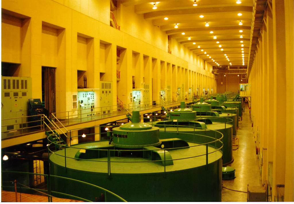
Below, some of the generators at Grand Coulee Dam.


There are other, less massive hydroelectric power plants, of course. Many Hydro power plants are called "run-of-the-river" plants. They will have a dam, to provide a bit of elevation and increase water pressure, but they will not have a reservoir. The output of these hydroelectric power plants is completely at the mercy of the flow of the river. Here is an example of a run-of-the-river dam:

Notice that this dam does not impound a vast amount of water behind it, so when the river runs low, so does the power output. This is not the case with a powerhouse with a reservoir of water.
This is just a brief overview of how hydroelectric power works. If you are more interested, here are a couple of quick links:
History of the LADWP power projects
Everything you need to know about Hydroelectric Energy
I'm not that interested. Hydro is pretty dam (pun intended) boring - except when it fails. That's what I am interested in! You often read about a fire, a meltdown or explosion at a thermal plant. I bet you didn't know that hydro plant failures have killed more people than any other type of power plant. We will look into that more in the next few posts...
Hydropower is the energy that can be harvested from falling water. Because water is so dense, even a modest drop in elevation can perform significant work. Hydropower has been around since ancient times, most commonly by harnessing the rotary motion provided by water wheels. The water wheel would then be geared to a grain mill, lumber mill, or textile mill.
Waterwheels could be arranged with water flowing over the top - "overshot", or dipped into a fast running current, "undershot".
With the advent electrical power, the waterwheel was eventually abandoned in favor of more efficient and controllable means of capturing the power from running water.
The mechanism that replaced the waterwheel was the turbine. The first turbine entering widespread use was called the "Francis Turbine". It was invented in 1848 for a textile factory in Massachussets. This design is a reaction turbine with quite high efficiency, and it is still widely used today.
Water turbines develop greater power when there is more flow and pressure. The flow of a river varies over time according to the whims of nature, but of course the water can be held in a reservoir and released as needed. The other advantage of a reservoir is that a dam increases the height of the water behind it, increasing the pressure. As the water level rises behind the dam, so does the pressure at the turbine inlet. (In hydropower speak, this pressure is called "head") To maximize the head - the distance between the surface of the water behind the dam and the turbine inlet - turbines are located at the bottom of the dam, with a generators installed just above them in a large machinery hall.
Cutaway of the action: (Image courtesy of the US Army Corps of Engineers)

Below, the installation of a Francis Turbine at Grand Coulee Dam in Washington State, late 1930's. This turbine drives a 125 Megawatt generator.

One of the larger turbines added to Grand Coulee in the 1970's. This drives a 600 MW generator. Grand Coulee can generate up to 6800 MW, making it the largest power station in the U.S.

Below, some of the generators at Grand Coulee Dam.
Below, a panoramic picture of Grand Coulee Dam. The new powerhouse is at the left.

There are other, less massive hydroelectric power plants, of course. Many Hydro power plants are called "run-of-the-river" plants. They will have a dam, to provide a bit of elevation and increase water pressure, but they will not have a reservoir. The output of these hydroelectric power plants is completely at the mercy of the flow of the river. Here is an example of a run-of-the-river dam:

Notice that this dam does not impound a vast amount of water behind it, so when the river runs low, so does the power output. This is not the case with a powerhouse with a reservoir of water.
This is just a brief overview of how hydroelectric power works. If you are more interested, here are a couple of quick links:
History of the LADWP power projects
Everything you need to know about Hydroelectric Energy
I'm not that interested. Hydro is pretty dam (pun intended) boring - except when it fails. That's what I am interested in! You often read about a fire, a meltdown or explosion at a thermal plant. I bet you didn't know that hydro plant failures have killed more people than any other type of power plant. We will look into that more in the next few posts...
Wednesday, November 25, 2015
Emergency Power - Portable Generators and Power Inverters.
After that last post about the wind storm, it got me thinking about alternate sources of electrical power. There are two readily available ways to get emergency AC (alternating current) power. You can use a power inverter, or you can use a generator.
Saturday, November 21, 2015
So we had a little windstorm...
On November 17th a windstorm blew across Washington, Northern Idaho, and Montana. Central Washington lost power lines due to high winds snapping power poles. The rest of the region lost power lines due to trees falling on them.
The trees were hard on other things, like dwellings, vehicles, and pedestrians :(
The trees were hard on other things, like dwellings, vehicles, and pedestrians :(
Thursday, November 13, 2014
Steam Turbine Outage
This may or may not be an interesting topic to the random readers that drop by here. I honestly don't know. I've been around steam turbines my entire adult life, and have never given the shaft sealing system much thought - until we had a seal failure that ended up with the accumulation of a bit of new knowledge, which I share here.
As you would guess, steam tends to leak out of a steam turbine at the high pressure end, where steam enters the turbine, and air tends to leak in at the exhaust, where the final stage of the turbine is at 1-3 inHg Absolute pressure (25-27 inHg vacuum). Steam turbines are not sealed like pumps. Pumps use flexible packing or mechanical seals, that actually come in contact with the shaft. Steam turbines do not seal this way, due to large swings in operating temperature from cold to running. Instead turbines are sealed using steam!
I took a quite a few photos while the steam turbine was apart for the seal repair, and thought they were interesting enough to put up. The steam turbine is a General Electric model A-10.
Most modern steam turbines are what we call "self-sealing". What that means is that they only need to be supplied with sealing steam during startup and shutdown. After the turbine reaches a certain load (5-20%), leak-off from the turbine supplies the seal steam, and external sources can be shut down. If there is any excess leak-off, and the seal steam supply pressure gets above the setpoint, a seal steam dump valve opens, and dumps the excess steam into the main condenser.
The symptoms of a failed steam sealing system are these:
- The seal steam dump valve is 100% open, and yet the seal steam header pressure is still too high.
- Water vapor and condensation coming from the Lube Oil System vents.
- Increasing Lube Oil Tank level due to steam ingress and water contamination/condensation.
Note: Water enters the lube oil system because the turbine shell is very close to the bearing housing. So as steam leaks out along the shaft of the turbine, it can leak right into the adjacent bearing housing. The lube oil system is kept under a light vacuum so that air will leak into the bearing housings, rather than oil leaking out. This will help pull in steam if the steam seal is leaking.
First of all, before any work can begin, the steam turbine must be shut down and allowed to cool.
Following the shutdown, the steam turbine has to be continuously rolled at low speed (typically 4-10 RPM) for about 3 days. Steam turbines operate at very high steam pressures and temperatures, and as a result, the turbine shell is very thick at the high pressure end. The shell is also insulated for thermal efficiency as well as for safety. For these reasons it takes several days before the turbine is cool enough to stop turning.
The purpose of rolling the turbine is to prevent warping the rotor. If the rotor is allowed to stop, it will develop a bow. Once a bow develops, it may sometimes work itself out when the steam turbine is returned to service; the rotor, reheated by steam, becomes ductile again and the bow mostly disappears. Other times, with severe bowing, the machine cannot even be started due to increased vibration caused by the off-center mass of the rotor. The damaged rotor will require machining and the addition of balance weights to compensate for the bowing, if not complete replacement. Needles to say, it's preferable to keep the steam turbine on the turning gear until it cools down.
Interestingly, a steam turbine rotor does not sag if it cannot be rolled during cooldown. Instead it humps up in the middle, because of the temperature differential between the top and bottom of the turbine shell. It is not unusual to have a 200 degree temperature differential between the top of the shell and the bottom. As heat rises inside the shell, the bottom part of a motionless rotor will contract more quickly than the top, which then bows the rotor upwards.
Onward now to the bits and pieces of a smallish high pressure steam turbine outage...
Below, a worker uses a sledge hammer to remove a nut from a through-bolt on the high pressure turbine shell.

Below: The top of the High Pressure turbine shell. The far end (burnt off paint) is the high pressure steam inlet.

Below, two workers removing the high pressure inlet steam seals.

Below: Another image of the high pressure turbine. At the bottom left corner on the rotor, are holes for balance weights. Next is the steam sealing section, then a series of discs with tiny blades at the end. These discs are the 10 stages of the high pressure steam turbine. The generator is the big thing to the right. Notice how thick the steam turbine shell is - This is why it takes three days to cool the steam turbine down from 1050 degrees F.

This is a close-up of the high pressure steam sealing section, with the packing (or labyrinth seals) removed. High pressure (up to 1800 psi) steam enters the turbine just to the left of the disk on the right hand side, and then flows off to the right. At 1800 PSI, steam would tend to leak out along the shaft and be a hazard for everyone around, as well as causing a loss of efficiency. To prevent this, steam turbines use labyrinth seals.

Below: Side view of a labyrinth seal. These segments slide into the grooves in the sealing section of the shell, sitting very close to, but not rubbing on the rotor. The purpose is to make the steam pass through a "labyrinth", or a series of very tight passages, losing a little pressure with each ridge. At the left end of the seal in the photo above, a small fan draws off the tiny amount of leak-off steam and condenses it for re-use. Clever!

Below, labyrinth seals (or packing) installed in the grooves on the high pressure turbine. Interestingly these are held in place by springs that are merely short flat pieces of steel These springs press against the inside of the packing gland and the outside of the labyrinth seal. Several of these springs were found to be broken during this outage.

The picture below shows a part of the steam turbine that is contained within the lube oil system. At the right is a journal bearing. This supports the aft end of the high pressure turbine (which is just off the picture to the right). You can see a wire coming off this journal bearing, which is used to transmit the temperature of the bearing metal. To the left of the bearing is a flat metal flange on the shaft. This is used to determine rotor expansion. The shaft expands quite a bit as the steam turbine goes from a cold condition to the normal operating temperature of 1050 degrees F. The coil of blue wire connects the rotor expansion position sensor to the monitoring system. The big gear is for rolling the rotor when the steam turbine is not in operation. The big round flange with all the holes in it is the coupling which connects the generator to the turbine.

Below, the bearings at the other end of the high pressure steam turbine. In the center is a journal bearing, with thrust bearings to either side. The journal bearing supports the shaft, and keeps it from moving in a radial (side to side or up and down) direction. The purpose of the thrust bearing is to keep the shaft from moving axially (left to right) . The shiny flanges with no holes in them are a part of the rotor called thrust collars. The shiny things just inside them are the thrust bearings. This section of the steam turbine is continuously supplied with oil to cool and lubricate the components.


These looked in pretty bad shape as well. Obviously there had been some heating and breakdown of the oil into carbon deposits.

Replacement labyrinth seals installed on the high pressure turbine lower half. Note the serpentine path that leak-off steam must travel.

High pressure steam turbine back together and being fitted with brand new insulating blankets.

Because one end of the rotor is held in place by the thrust bearing, the other end of the rotor grows as steam heats it. It's quite possible to have rubs if the expansion of the rotor gets too far ahead of the shell. That's why you will find rotor expansion proximitors (Below). These little pucks monitor exactly how much the rotor has expanded.

This is one of the few outages I have had time to take pictures and learn a few things, because on scheduled outages, I usually have assignments that keep me too busy for that. Was fun to learn, fun to share.
NOTE: There is a continuation to this post with some further useful information HERE.
Sunday, July 28, 2013
Summer Vacation
The family just returned from summer vacation. It was an exhausting whirlwind of a trip, and I don't intend to repeat that sort of vacation again. It took 3 days of driving to get to SoCal, and 3 days to return, with a lot of side trips while we were there. Disneyland, the Ringling Circus, Bakersfield, and Morro Bay.
Although we saw some really cool things and got to visit old friends, we didn't go anywhere that was nicer than where I live. Hmmm. Maybe that's why this is a vacation spot...
That said, I did get some really cool pictures of places that we visited. One of those places was Bodie, California, a turn of the century ghost town. There is a lot more there than the pictures posted here. I just wanted to share the cool old steam and electric power stuff :)


While we were at Morro Bay I happened to see DSRV-2, the "Avalon", on display. This is a little electric deep-diving submarine. "DSRV" stands for "Deep Submergence Rescue Vehicle".
During the cold war, the Navy had a DSRV stationed on each coast. In the event a military submarine sunk, the Navy had the ability to load these into a cargo aircraft and quickly get it to the sunken boat, to hopefully rescue survivors.
Unfortunately for the crew of the submarine Kursk, this DSRV hatch would not have mated to the Russian submarine hatch. Also if I recall correctly, the hatch was too damaged to open, probably due to hull flexing and deforming after impacting the bottom.

Here are the specs for DSRV-2.
Side note: A shipmate of mine transferred to this little guy back in the 1980's. He said that he finally got a chance to look out at the ocean while submerged (military subs have no windows, for obvious reasons). For his first dive, they took Avalon clear to the bottom off the coast of San Diego, put him in front of a window, then turned on the lights. He said there was nothing to see but sand and a few empty beer cans. Hahaha!
Although we saw some really cool things and got to visit old friends, we didn't go anywhere that was nicer than where I live. Hmmm. Maybe that's why this is a vacation spot...
That said, I did get some really cool pictures of places that we visited. One of those places was Bodie, California, a turn of the century ghost town. There is a lot more there than the pictures posted here. I just wanted to share the cool old steam and electric power stuff :)
Below, a skid-mounted boiler

A steam piston engine for running the mine elevator. Note the journal for the shaft at the far end.

The flywheel and shaft that were attached to the steam engine. This wheel is enormous. The shaft is a foot across.

A small AC generator. This is about 3 ft across.

We also went to Twin Lakes at Mammoth Village. A very pretty place, although after a year of living in northern Idaho, the forests in California looked pretty sparse and dry.

On the way home, we drove over White's Pass, between Mt. Ranier to the north and Mt. St. Helens to the south. Below is a photo of St. Helens. Unfortunately, there was a lot of moisture haze in the air, so I didn't get a clear shot. This is the northwest side of the mountain that blew out in 1980.

Mt. Ranier, another dangerous volcano. The forest here is quite lush.

Upper Clear Creek Falls. The water spreads way out, maybe 20 ft across and maybe an inch deep, before pooling together again at the bottom.

Lower Clear Creek Falls.

While we were at Morro Bay I happened to see DSRV-2, the "Avalon", on display. This is a little electric deep-diving submarine. "DSRV" stands for "Deep Submergence Rescue Vehicle".
During the cold war, the Navy had a DSRV stationed on each coast. In the event a military submarine sunk, the Navy had the ability to load these into a cargo aircraft and quickly get it to the sunken boat, to hopefully rescue survivors.
Unfortunately for the crew of the submarine Kursk, this DSRV hatch would not have mated to the Russian submarine hatch. Also if I recall correctly, the hatch was too damaged to open, probably due to hull flexing and deforming after impacting the bottom.

Here are the specs for DSRV-2.
| Builder: | Lockheed Missiles and Space, Co., Sunnyvale, California, USA |
| Power Plant: | Electric motors, silver/zinc batteries, one shaft, 15 shaft horsepower (11 kW), four thrusters, 7.5 horsepower (6 kW). |
| Length: | 49 ft (15 m) |
| Beam: | 8 ft (2.4 m) |
| Displacement: | 38 tons (39 metric tons) |
| Speed | 4 knots (7 km/h) |
| Maximum depth: | 5,000 ft (1500 m) |
| Sonar: | Search and navigation |
| Ships: | Mystic (DSRV 1) |
| Avalon (DSRV 2) | |
| Crew: | Two pilots, two rescue personnel and the capacity for 24 passengers |
Side note: A shipmate of mine transferred to this little guy back in the 1980's. He said that he finally got a chance to look out at the ocean while submerged (military subs have no windows, for obvious reasons). For his first dive, they took Avalon clear to the bottom off the coast of San Diego, put him in front of a window, then turned on the lights. He said there was nothing to see but sand and a few empty beer cans. Hahaha!
Saturday, June 22, 2013
AC vs. DC Power
At the end of the 19th century, an epic battle was shaping up. On one side were Thomas Edison and Lord Kelvin, who advocated using Direct Current (DC) power distribution systems. On the Alternating Current side of the battle were George Westinghouse and Nikolai Tesla (and nature).
The battle was known as the "War of the Currents". DC power systems had already been developed and in use in the United States for several years, and were the standard in use in the 1880s. From Wiki:
"During the initial years of electricity distribution, Edison's direct current was the standard for the United States, and Edison did not want to lose all his patent royalties. Direct current worked well with incandescent lamps, which were the principal load of the day, and with motors. Direct-current systems could be directly used with storage batteries, providing valuable load-leveling and backup power during interruptions of generator operation. Direct-current generators could be easily paralleled, allowing economical operation by using smaller machines during periods of light load and improving reliability. At the introduction of Edison's system, no practical AC motor was available. Edison had invented a meter to allow customers to be billed for energy proportional to consumption, but this meter worked only with direct current. The transformation efficiency of the early open-core bipolar transformers was very low. Early AC systems used series-connected power distribution systems, with the inherent flaw that turning off a single lamp (or the disconnection of other electric device) affected the voltage supplied to all others on the same circuit. The direct current system did not have these drawbacks as of 1882, giving it significant advantages."
Innovation would shortly end most of the advantages held by Direct Current however, and by 1896 the war would be over. The first innovation was a high-efficiency transformer. This allowed conversion of AC power to very high voltage for transmission with low losses, and conversion to low voltage near the end user. DC power was generated at 110 volts, and due to line losses at this voltage, there had to be a power plant within a mile or so of the end-user. This arrangement would require a power plant to be installed every mile or so! A great arrangement for Thomas Edison, but not so great for everyone else.
What actually caused DC to lose the Battle of the Currents is an electrical relationship, stated in Ohm's Law. Ohm's law says that Power is equal to Voltage times Current, or P = V x C. A corollary of that law is that Power is equal to the square of current times resistance, or P = I^2 x R. This corollary is what killed Direct Current as a means of using electrical power.
In any electrical system, transmission lines will have a certain resistance to current flow. This resistance causes heating, and reduces the ability of the transmission line to carry full load. This is the P - I^2 x R portion of Ohm's Law. Doubling current increases resistive heating by 4 times, and this power that is wasted heating up the power line is lost to the end user.
Therefore, with a semi-understanding of Ohm's law, P = V x C, we can see we need to minimize current if for a given Power to transmit power over any kind of distance. This is done by raising voltage as high as practical. With a transformer we can adjust AC voltage at will, whereas DC has to be generated at the desired end-user voltage, and the entire system must run at that voltage.
There is another reason AC power won the battle: It is simpler to work with at the generator. With a DC machine, the power is produced on the rotor, and must be removed using carbon brushes from the commutator. There are limits to how much current can pass through these brushes, so a typical power plant would have several small machines, each producing a small amount of power.
With an AC generator, the electromagnetic field rotates, and power is produced in the stationary windings of the machine. Because there is no need to pull power from a rotating member, the AC generator can make a great deal more power than its DC counterpart. The largest Dynamo ever built could convert 500 horsepower to DC power. An equivalent physical-size AC machine would be able to convert 10,000 horsepower, with far less complexity and maintenance.
Looking at the small machine below, we can guess a few things:

In the end, AC (rightfully) won the battle, and so now we live in an Alternating Current world. The Wiki version of this fascinating story is here.
And here is a video describing the battle!
https://www.youtube.com/watch?v=xyQfrzBfnDU
The battle was known as the "War of the Currents". DC power systems had already been developed and in use in the United States for several years, and were the standard in use in the 1880s. From Wiki:
"During the initial years of electricity distribution, Edison's direct current was the standard for the United States, and Edison did not want to lose all his patent royalties. Direct current worked well with incandescent lamps, which were the principal load of the day, and with motors. Direct-current systems could be directly used with storage batteries, providing valuable load-leveling and backup power during interruptions of generator operation. Direct-current generators could be easily paralleled, allowing economical operation by using smaller machines during periods of light load and improving reliability. At the introduction of Edison's system, no practical AC motor was available. Edison had invented a meter to allow customers to be billed for energy proportional to consumption, but this meter worked only with direct current. The transformation efficiency of the early open-core bipolar transformers was very low. Early AC systems used series-connected power distribution systems, with the inherent flaw that turning off a single lamp (or the disconnection of other electric device) affected the voltage supplied to all others on the same circuit. The direct current system did not have these drawbacks as of 1882, giving it significant advantages."
Innovation would shortly end most of the advantages held by Direct Current however, and by 1896 the war would be over. The first innovation was a high-efficiency transformer. This allowed conversion of AC power to very high voltage for transmission with low losses, and conversion to low voltage near the end user. DC power was generated at 110 volts, and due to line losses at this voltage, there had to be a power plant within a mile or so of the end-user. This arrangement would require a power plant to be installed every mile or so! A great arrangement for Thomas Edison, but not so great for everyone else.
What actually caused DC to lose the Battle of the Currents is an electrical relationship, stated in Ohm's Law. Ohm's law says that Power is equal to Voltage times Current, or P = V x C. A corollary of that law is that Power is equal to the square of current times resistance, or P = I^2 x R. This corollary is what killed Direct Current as a means of using electrical power.
In any electrical system, transmission lines will have a certain resistance to current flow. This resistance causes heating, and reduces the ability of the transmission line to carry full load. This is the P - I^2 x R portion of Ohm's Law. Doubling current increases resistive heating by 4 times, and this power that is wasted heating up the power line is lost to the end user.
Therefore, with a semi-understanding of Ohm's law, P = V x C, we can see we need to minimize current if for a given Power to transmit power over any kind of distance. This is done by raising voltage as high as practical. With a transformer we can adjust AC voltage at will, whereas DC has to be generated at the desired end-user voltage, and the entire system must run at that voltage.
There is another reason AC power won the battle: It is simpler to work with at the generator. With a DC machine, the power is produced on the rotor, and must be removed using carbon brushes from the commutator. There are limits to how much current can pass through these brushes, so a typical power plant would have several small machines, each producing a small amount of power.
With an AC generator, the electromagnetic field rotates, and power is produced in the stationary windings of the machine. Because there is no need to pull power from a rotating member, the AC generator can make a great deal more power than its DC counterpart. The largest Dynamo ever built could convert 500 horsepower to DC power. An equivalent physical-size AC machine would be able to convert 10,000 horsepower, with far less complexity and maintenance.
Looking at the small machine below, we can guess a few things:
- The commutator segments would require regular care to ensure they remained insulated from each other.
- Maintenance of brushes and tension would be an ongoing affair.
- Due to low voltage, the output current would be large. You can see how fat the output leads are.
- With such high currents, moving this electricity would require vast amounts of copper.

In the end, AC (rightfully) won the battle, and so now we live in an Alternating Current world. The Wiki version of this fascinating story is here.
And here is a video describing the battle!
https://www.youtube.com/watch?v=xyQfrzBfnDU
Steam Power and Electricity - Dynamos
Steam engines were invented around 1700 AD. Using a steam engine to turn a generator in order to make electricity would have to wait for another 130 years. Electricity was not understood, and the earliest generators used electrostatic principles to push electrons around. Surviving examples of these static-electricity type generators include the Wimshurst generator and the Van de Graaf generator.
Subscribe to:
Posts (Atom)