"The purpose of life is not to be happy. It is to be useful, to be honorable, to be compassionate, to have it make some difference that you lived." - Ralph Waldo Emerson

An advertisement-free blog about motorcycling, Northern life, home improvement, power plants, submarines, nuclear stuff, and a few other off-beat subjects. Comments are welcome. (Image is the Selway Crags in Northern Idaho)
Showing posts with label Gas Turbine. Show all posts
Showing posts with label Gas Turbine. Show all posts
Friday, February 07, 2025
February - Calm before the storm


Monday, May 13, 2024
Outage addendum 2
"What the superior man seeks is in himself. What the small man seeks is in others." - Confucius
Monday, January 29, 2024
Monday, January 15, 2024
Life in the washing machine 'spin cycle'
"It is the classic fallacy of our time that a moron run through a university and decorated with a Ph.D. will thereby cease to be a moron." - H. L. Mencken
Sunday, April 30, 2023
Outage time again
"Before you diagnose yourself with depression or low self-esteem, first make sure that you are not, in fact, just surrounded by assholes." - William Gibson
Monday, December 26, 2022
The Greatest Opponent Ever Faced by the ruling class: Reality
"No amount of evidence will ever persuade an idiot." - Mark Twain
Sunday, January 23, 2022
Compressor Stall on Industrial Turbines
"Never value the advantages derived from anything involving breach of faith, loss of self-respect, hatred, suspicion, or execration of others, of insincerity or the desire for something which has to be veiled or hidden." - Marcus Aurelius
Sunday, November 30, 2014
America's fastest locomotive
M-497, nicknamed "The Black Beetle". This was the fastest locomotive to operate in the US. It was an experimental locomotive build and tested by the New York Central Railroad. The locomotive was actually a Budd Rail Diesel Car (RDC-3) powered by two second-hand GE J47-19 turbojet engines. These engines had originally been mounted on a B-36D Peacemaker for take-off assist and dash speed over the bombing target. The B-36 was active from 1946 to 1959
Below: B-36 Peacemaker. Note the outboard engines are a pair of turbojets...

Below is a photo of a Budd Rail Diesel Car. These were individually powered rail cars, i.e. passenger or mail coaches that also contained two small diesel engines. These single cars were used in rural areas where passenger traffic was light. Photo courtesy of Bevis R. W. King.

Below is a photo of our hybrid of the Budd Rail Diesel Car and the B-36 turbojets. The M-497 in 1966, with the B-36 engines mounted up front. An aerodynamic nose was added to the locomotive, and the diesel engines were removed.

M-497 on one of the test runs, which took place between Butler, Indiana and Stryker, Ohio.

Another picture of M-497, clearly moving at high speed.

This testing was done on straight track in good condition and with no modifications. The top speed was measured at 183.68 mph - a record that was set in 1966, and which unfortunately has not been broken since in the US. A passenger train going that fast would certainly be awesome. I'm pretty sure it could be done....

Below: B-36 Peacemaker. Note the outboard engines are a pair of turbojets...
Below is a photo of a Budd Rail Diesel Car. These were individually powered rail cars, i.e. passenger or mail coaches that also contained two small diesel engines. These single cars were used in rural areas where passenger traffic was light. Photo courtesy of Bevis R. W. King.
Below is a photo of our hybrid of the Budd Rail Diesel Car and the B-36 turbojets. The M-497 in 1966, with the B-36 engines mounted up front. An aerodynamic nose was added to the locomotive, and the diesel engines were removed.
M-497 on one of the test runs, which took place between Butler, Indiana and Stryker, Ohio.
Another picture of M-497, clearly moving at high speed.
This testing was done on straight track in good condition and with no modifications. The top speed was measured at 183.68 mph - a record that was set in 1966, and which unfortunately has not been broken since in the US. A passenger train going that fast would certainly be awesome. I'm pretty sure it could be done....
Saturday, March 01, 2014
Compressor Destruction :(
I have always been amazed by how quickly and destructively large powerful machines can fail. I happened upon some pictures recently of an Industrial Combustion Turbine failure, brought on by icing. The other type of combustion turbine is aero, like you might find on an aircraft. Industrial (or "Frame") turbines are quite heavy and cannot be flown.
A gas turbine consists of three sections: Compressor, Combustor, and Turbine. At the inlet of the compressor, air pressure is reduced because the compressor is sucking air in. This inlet pressure drop also causes a slight temperature drop, which is how this turbine's problem began.
Take a look at this video of an aircraft testing an aero turbofan engine. You can see water vapor entering the engine. This water vapor appears because the drop in pressure (a.k.a. suction) at the compressor inlet is also causing air temperature to drop. The temperature is falling below the dewpoint - that is, moisure present in the air is condensing suddenly due to the drop in temperature. Those swirls are condensing water vapor entering the engine.
Certain weather conditions, however, will cause moisture in the air to change from harmless vapor to ice. Relative humidity must be high, ambient temperature has to be near the dew point, and temperature has to be near or below freezing. Remember that air temperature drops as it enters the compressor, so the temperature doesn't have to be 32 degrees. Inlet icing can occur with ambient temperatures as high as 38 degrees.
Icing is only an issue for the first row of compressor blades, because they are the coldest ones. Water vapor can form, and freeze to the blades, if they are cold enough. Icing is not a problem further inside the compressor, because as the air pressure increases, the air temperature also increases. In fact, at the discharge of the compressor of a stationary gas turbine, the air temperature is about 700 degrees F.
If necessary, a portion of this 700 degree air can be "bled off", and brought forward to the inlet. This raises the inlet temperature just enough to prevent ice from forming. This is called the Inlet Bleed Heat system. You take a small hit on engine output, but it definitley beats scrapping the engine.
Gas Turbine compressors are designed using complex fluid dynamics calculations to maximize airflow. Maximizing airflow requires minimizing vortex formation, and minimizing interstage air leakage along the shaft and casing. Thus everything inside is machined with very fine clearances for high efficiency. For these reasons the blades are machined with pretty tight tolerances, and normally the airflow in the machine is in line with what the software calculated.
Inlet icing throws all that fluid modeling out the window, because if the blades are covered in ice, airflow will be erratic.
This machine may have experienced ice buildup on the stationary compressor blades in the first row. The ice caused the air to flow unevenly onto the the rotating blades. Each time a rotating blade passed a stationary blade with ice on it, turbulent/uneven airflow would cause a rocking motion as the rotating blade was buffeted by varying amounts of air. This would actually be a very high speed vibration, since the rotor spins at 60 times per second. The vibration created metal fatigue at the base of the blade (like bending a coat hangar over and over until it snaps in two) and eventually the blade came loose from the rotor.
With the rotor spinning at 60 revolutions per second, the blade had plenty of centrifugal (centripetal) stress to shear it off, once the base had gathered enough cyclical fatigue to create a crack.
What followed after the compressor blade released compounded the failure. It was pulled through the machine by the air stream and impacted most (perhaps all) of the other blades. What a mess. Moral of the story: Don't allow the inlet to ice up.

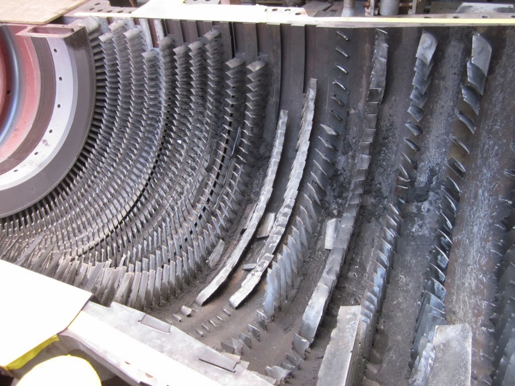
Below: A severely damaged compressor. It appears that all of this damage was caused by a single blade passing through the compressor. (Inlet is to the left side, so the loose blade came from that row). None of the blades on this rotor escaped harm. It is not clear if the combustor section or turbine section were also damaged.


A gas turbine consists of three sections: Compressor, Combustor, and Turbine. At the inlet of the compressor, air pressure is reduced because the compressor is sucking air in. This inlet pressure drop also causes a slight temperature drop, which is how this turbine's problem began.
Take a look at this video of an aircraft testing an aero turbofan engine. You can see water vapor entering the engine. This water vapor appears because the drop in pressure (a.k.a. suction) at the compressor inlet is also causing air temperature to drop. The temperature is falling below the dewpoint - that is, moisure present in the air is condensing suddenly due to the drop in temperature. Those swirls are condensing water vapor entering the engine.
Certain weather conditions, however, will cause moisture in the air to change from harmless vapor to ice. Relative humidity must be high, ambient temperature has to be near the dew point, and temperature has to be near or below freezing. Remember that air temperature drops as it enters the compressor, so the temperature doesn't have to be 32 degrees. Inlet icing can occur with ambient temperatures as high as 38 degrees.
Icing is only an issue for the first row of compressor blades, because they are the coldest ones. Water vapor can form, and freeze to the blades, if they are cold enough. Icing is not a problem further inside the compressor, because as the air pressure increases, the air temperature also increases. In fact, at the discharge of the compressor of a stationary gas turbine, the air temperature is about 700 degrees F.
If necessary, a portion of this 700 degree air can be "bled off", and brought forward to the inlet. This raises the inlet temperature just enough to prevent ice from forming. This is called the Inlet Bleed Heat system. You take a small hit on engine output, but it definitley beats scrapping the engine.
Gas Turbine compressors are designed using complex fluid dynamics calculations to maximize airflow. Maximizing airflow requires minimizing vortex formation, and minimizing interstage air leakage along the shaft and casing. Thus everything inside is machined with very fine clearances for high efficiency. For these reasons the blades are machined with pretty tight tolerances, and normally the airflow in the machine is in line with what the software calculated.
Inlet icing throws all that fluid modeling out the window, because if the blades are covered in ice, airflow will be erratic.
This machine may have experienced ice buildup on the stationary compressor blades in the first row. The ice caused the air to flow unevenly onto the the rotating blades. Each time a rotating blade passed a stationary blade with ice on it, turbulent/uneven airflow would cause a rocking motion as the rotating blade was buffeted by varying amounts of air. This would actually be a very high speed vibration, since the rotor spins at 60 times per second. The vibration created metal fatigue at the base of the blade (like bending a coat hangar over and over until it snaps in two) and eventually the blade came loose from the rotor.
With the rotor spinning at 60 revolutions per second, the blade had plenty of centrifugal (centripetal) stress to shear it off, once the base had gathered enough cyclical fatigue to create a crack.
What followed after the compressor blade released compounded the failure. It was pulled through the machine by the air stream and impacted most (perhaps all) of the other blades. What a mess. Moral of the story: Don't allow the inlet to ice up.
Below: A new, clean compressor. Inlet to the left side, discharge is near the circular flange to the right.

Below: A severely damaged compressor. It appears that all of this damage was caused by a single blade passing through the compressor. (Inlet is to the left side, so the loose blade came from that row). None of the blades on this rotor escaped harm. It is not clear if the combustor section or turbine section were also damaged.

With the rotor removed, you can see that most of the stationary blades are also damaged. The case will undoubtedly need some repairs as well. Sad sad stuff here.
Tuesday, April 02, 2013
Another Gas Turbine Cutaway
Since the Gas Turbine Cutaway post appears to be one of the most-viewed on the blog, here's another one. This is a really odd design that Alstom came up with back in the 1980s.
It's a pretty cool design, and it kind of reminds me of a model airplane engine. This is the Alstom GT11N. I think it puts out about 100 Megawatts. What's interesting about this design is that combustion occurs outside of the turbine proper, in a "silo combustor".
Air is drawn in at the right side in this picture, compressed in several stages, and then it flows up just inside the wall of the the large cylinder at the center. This pre-heats the combustion air while keeping the inner combustion liner cool and preventing it from melting. The air is blended with natural gas (or fuel oil) at the top of the silo combustor. The fuel/air mixture is burned as it travels down in the silo, then the hot gases are routed into a donut called the hot gas casingthat spreads them all around the turbine shaft, where they are allowed to expand and drive the turbine.

Here is another picture (actually an advertisement) that shows some of the parts in the gas flowpath.
 I don't know much more about this machine than this. It doesn't appear to have been too successful commercially, because there isn't much on the web about them, and the axial combustion scheme appears to be the dominant technology. Still, I thought this was a cool idea...
It's a pretty cool design, and it kind of reminds me of a model airplane engine. This is the Alstom GT11N. I think it puts out about 100 Megawatts. What's interesting about this design is that combustion occurs outside of the turbine proper, in a "silo combustor".
Air is drawn in at the right side in this picture, compressed in several stages, and then it flows up just inside the wall of the the large cylinder at the center. This pre-heats the combustion air while keeping the inner combustion liner cool and preventing it from melting. The air is blended with natural gas (or fuel oil) at the top of the silo combustor. The fuel/air mixture is burned as it travels down in the silo, then the hot gases are routed into a donut called the hot gas casingthat spreads them all around the turbine shaft, where they are allowed to expand and drive the turbine.

Here is another picture (actually an advertisement) that shows some of the parts in the gas flowpath.

Monday, June 05, 2006
JT8D turbofan

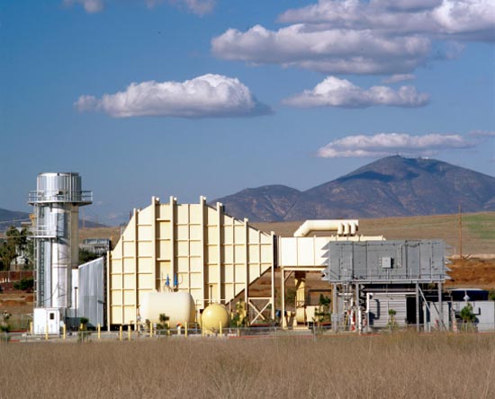
This is a cutaway of the impressive Pratt-Whitney JT8D turbofan. It's an aeroderivative engine used in peaking power plants, and the main competition to the GE LM2500.

A photo of the inlet end.
These are the engines I alluded to in a previous post that actually produce thrust (actually expanding hot gas) in a power plant environment, rather than shaft output. The engine rests on a stand, with the inlet connected to an air filter by ductwork. The exhaust is directed into a turbo-expander (not unlike a water-wheel arrangement) that converts the expanding gas into rotating energy, with the shaft perpendicular to the direction of thrust. Impressive fact: A single low-bypass aircraft engine can provide about 23 Megawatts of electricity.
Aeroderivative engines are high-maintenance. They are frequently changed out when parts fail on them.
The advantage of this arrangement over the LM2500 is that no alignment is required. The fuel lines, instrumentation and duct work are removed, and the engine can be pulled. Replacement is the reverse. The LM2500 must be carefully aligned with the generator shaft in addition to all of the above items. It lengthens the downtime when failure occurs.
Below: JT8D installation. Looking at the exhaust into the turboexpander.

I have not operated these type plants much at all, but according to co-workers, the JT8D can handle a compressor stall better than the GE machines as well.
Here's a photo of a dual JT8D installation:
Fascinating early jet engine
I lifted the photo from Wiki, along with the explanation. I'll turn it over to the original author:

"One problem with these early designs, which are called centrifugal-flow engines, was that the compressor worked by "throwing" (accelerating) air outward from the central intake to the outer periphery of the engine, where the air was then compressed by a divergent duct setup, converting its velocity into pressure. An advantage of this design was that it was already well understood, having been implemented in centrifugal superchargers. However, given the early technological limitations on the shaft speed of the engine, the compressor needed to have a very large diameter to produce the power required. A further disadvantage was that the air flow had to be "bent" to flow rearwards through the combustion section and to the turbine and tailpipe.
Austrian Anselm Franz of Junkers' engine division (Junkers Motoren or Jumo) addressed these problems with the introduction of the axial-flow compressor. Essentially, this is a turbine in reverse. Air coming in the front of the engine is blown towards the rear of the engine by a fan stage (convergent ducts), where it is crushed against a set of non-rotating blades called stators (divergent ducts). The process is nowhere near as powerful as the centrifugal compressor, so a number of these pairs of fans and stators are placed in series to get the needed compression. Even with all the added complexity, the resulting engine is much smaller in diameter."
It's impressive that a single stage centrifugal compressor could accomplish the necessary compression to produce enough thrust to fly an aircraft. Then too I've seen home-made turbocharger conversions to turbine engines. They aren't quite this level of sophistication though! :)
Anyway, it's a cool cutaway and I wanted to share it.
Saturday, June 03, 2006
Gas turbine cut-aways and photos
Here are a few cutaways and photos of gas turbines.
(Click on any image to enlarge)
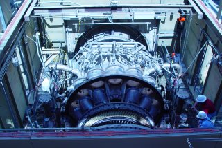
Above is a GE industrial turbine. Note that it is quite large and heavy, and how thick the casing is (bolting for the joints is near the bottom of the photo). Clearly this could never be mounted to an aircraft wing! The air intake is at the far end of the photo, while the exhaust is closest. The mass of smaller pipes is for fuel delivery to the combustors (which have been removed in this photo).
The turbine rotating blades are clearly visible in this picture. The first stage blades are exposed to very corrosive, very high temperature exhaust gas, and are ceramic coated to extend longevity - thus the yellow-ish color. Increasing firing temperatures increases the efficiency of the machines, so there is ongoing research to improve turbine blades. Although it cannot be seen in this photo, the compressor and turbine blades are all mounted on a single shaft that extends throughout the machine.
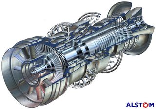
Above is a cut-away drawing of an Alstom industrial turbine. In this rendering, the exhaust is closest to the viewer, and with the cut-away, it is easy to see that the compressor and turbine blades are mounted on a common shaft. Air is drawn in at the far end, compressed, mixed with fuel and burned, and exhausted through the turbine.
This model is unique in that there are two combustion sections. The primary burn section is where the fuel nozzles enter at an angle. The exhaust gases pass through a single stage of turbine blades, then additional fuel is added and burned, and expanded through four more turbine stages. Theoretically in this manner firing temperatures can be reduced.
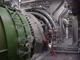
Here is a photo of the above machine.
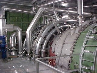
The same machine, from the other side.
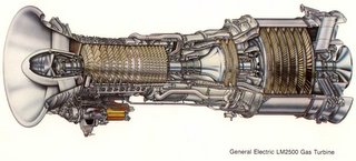
Lastly, here is an example of a commonly used aeroderivative gas turbine,the GE LM2500.
The air inlet is to the left. Air is compressed, fuel added and burned, which turns *two* turbines. This is a two-shaft machine. The first turbine is the high-speed turbine (two stages), which turns the compressor at about 9500 RPM.
The gas is not finished expanding however. It now passes to the second turbine - the power turbine. This second turbine is on a different shaft, rotating at 3600 RPM, which is coupled to an external generator (not shown). The technical term for this is "aerodynamic coupling". Basically the wind exiting the first turbine turns the second turbine.
(Click on any image to enlarge)
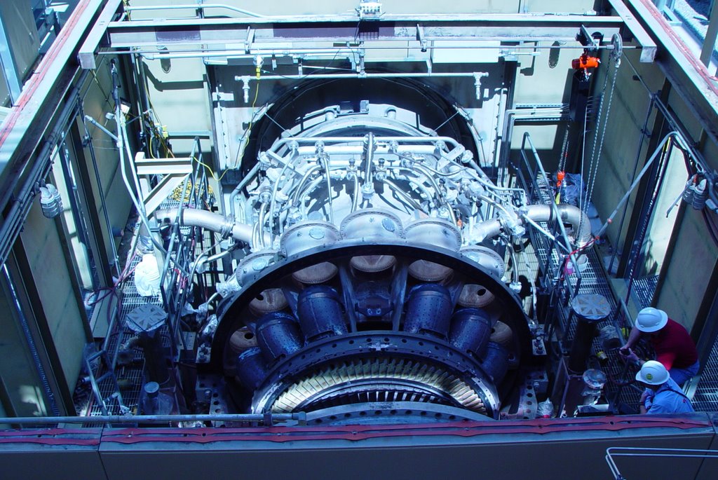
Above is a GE industrial turbine. Note that it is quite large and heavy, and how thick the casing is (bolting for the joints is near the bottom of the photo). Clearly this could never be mounted to an aircraft wing! The air intake is at the far end of the photo, while the exhaust is closest. The mass of smaller pipes is for fuel delivery to the combustors (which have been removed in this photo).
The turbine rotating blades are clearly visible in this picture. The first stage blades are exposed to very corrosive, very high temperature exhaust gas, and are ceramic coated to extend longevity - thus the yellow-ish color. Increasing firing temperatures increases the efficiency of the machines, so there is ongoing research to improve turbine blades. Although it cannot be seen in this photo, the compressor and turbine blades are all mounted on a single shaft that extends throughout the machine.
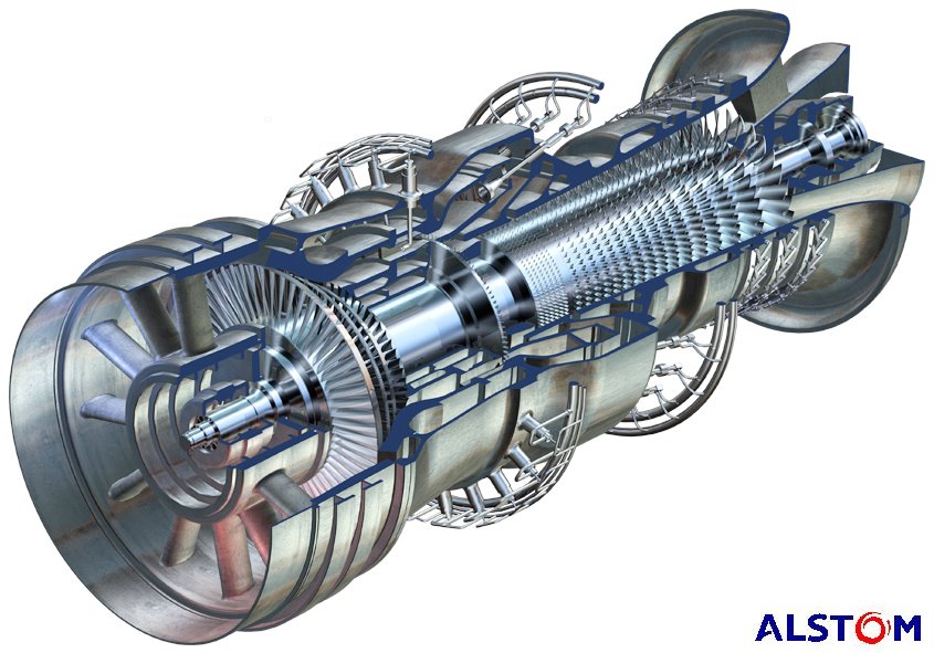
Above is a cut-away drawing of an Alstom industrial turbine. In this rendering, the exhaust is closest to the viewer, and with the cut-away, it is easy to see that the compressor and turbine blades are mounted on a common shaft. Air is drawn in at the far end, compressed, mixed with fuel and burned, and exhausted through the turbine.
This model is unique in that there are two combustion sections. The primary burn section is where the fuel nozzles enter at an angle. The exhaust gases pass through a single stage of turbine blades, then additional fuel is added and burned, and expanded through four more turbine stages. Theoretically in this manner firing temperatures can be reduced.
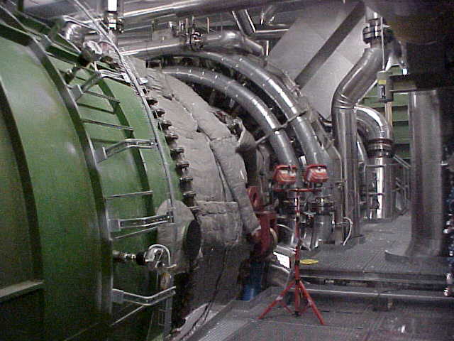
Here is a photo of the above machine.

The same machine, from the other side.
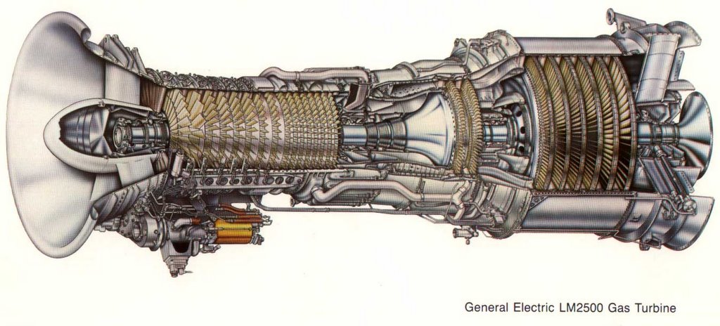
Lastly, here is an example of a commonly used aeroderivative gas turbine,the GE LM2500.
The air inlet is to the left. Air is compressed, fuel added and burned, which turns *two* turbines. This is a two-shaft machine. The first turbine is the high-speed turbine (two stages), which turns the compressor at about 9500 RPM.
The gas is not finished expanding however. It now passes to the second turbine - the power turbine. This second turbine is on a different shaft, rotating at 3600 RPM, which is coupled to an external generator (not shown). The technical term for this is "aerodynamic coupling". Basically the wind exiting the first turbine turns the second turbine.
Monday, May 29, 2006
Entering the jet age
In 2001 I was ready for a change. Many of my co-workers had vacated the coal-fired facility for brand-new gas turbine combined cycle power plants, and I was keen on getting into this exciting technology.
Note – small gas turbine power plants and turbine-powered gas pipeline compressing stations have been around for decades. A government/industry collaboration to advance gas turbine technology bore fruit in the late 1990’s. This started a massive building boom in large, highly efficient gas turbine plants.
I started looking around, and eventually was offered a position at a large (1048 Megawatt) facility that was then under construction. I went from burning dirt to operating one of the newest and most advanced gas turbines on the planet :) Fortunately it wasn't too difficult of a change, and being fully automated, it was not as challenging as the coal-burner to operate. I also learned that while gas turbine combustion and control logic are exceedingly complicated, the principle of operation is ridiculously simple. While the principle has been understood for a long time, it's only since WWII that practical gas turbines were actually built.
So how does a gas turbine work? As with coal furnaces, there are two major types that differ significantly from one another, although they both use the same principle, the Brayton Cycle.
Below is a diagram showing the four stages of combustion, both for a piston engine (the otto cycle) and a gas turbine (the brayton cycle). The similarities are that air is compressed, fuel is added and ignited, and work is derived from the expansion of the heated gases. The difference is that the piston engine delivers intermittent power, while the gas turbine compresses, burns, and delivers power continuously.
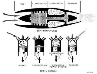
One footnote about the diagram: Most gas turbines used in power generation are not optimized to produce thrust (with one exception that I'm aware of), instead the turbine rotor will have an output shaft that spins at 3600 RPM, turning a generator.
The two types of gas turbines are calle aeroderivative and industrial. It's somewhat self-descriptive, except for the engineering finesse on each design. Aeroderivative engines are gas turbines originally designed for aircraft - they are light, high-revving, easily replaceable machines. In contrast, industrial gas turbines are heavy behemoths that turn at 3600 RPM and are not intended to be removed.
The simpler design, the industrial (or frame) engine, has a single shaft that has an axial compressor at one end, a combustion zone in the center, and a turbine at the exit end. How does it work? The compressor pulls in an enormous mass of filtered air and compresses it. Next, fuel is precisely metered and pre-mixed with the compressed air, and burned in a continuous process. The superheated air expands with great force trough several stages of turbine blades, which convert the expanding gas energy into rotational energy. Because the compressor and turbine are on the same shaft, the turbine provides the energy to drive the compressor, plus has extra power left over to run a generator. The shells on industrial turbines tend to be a couple of inches thick, so that a catastrophic failure will typically be contained within the shell.
In the aeroderivative design there are two rotors. One rotor is high-speed, typically operating at 9500-9700 RPM. This section contains the compressor, combustion zone and a high speed turbine to drive the compressor. In the exhaust path right behind the high speed turbine is a 'power turbine'. The power turbine is connected to a generator that turns at 3600 RPM. As the high speed turbine revs and generates more exhaust gas, the power turbine places more load on the generator. Failures on aeroderivative engines tend to be spectacular - the shells of the engines are light, being designed for aircraft, and when the high speed turbines fail, the blades are thrown at high velocity. Pieces of these turbines are often found outside their protective enclosures following a failure.
The current power plant design is called a "combined cycle" arrangement. In this case we have one or more gas turbines (Brayton Cycle) that operate a generator. The still-hot exhaust gas is then directed into a boiler to create steam and operate a steam turbine (Rankine cycle), increasing power output for the same quantity of fuel burned. Thus we combine cycles! Coupling the cycles yields efficiencies close to 60%. Coal burners and nukes run 30-35% if I recall correctly. Advanced simple cycle (stand alone) gas turbines hit about 40% efficiency.
Note – small gas turbine power plants and turbine-powered gas pipeline compressing stations have been around for decades. A government/industry collaboration to advance gas turbine technology bore fruit in the late 1990’s. This started a massive building boom in large, highly efficient gas turbine plants.
I started looking around, and eventually was offered a position at a large (1048 Megawatt) facility that was then under construction. I went from burning dirt to operating one of the newest and most advanced gas turbines on the planet :) Fortunately it wasn't too difficult of a change, and being fully automated, it was not as challenging as the coal-burner to operate. I also learned that while gas turbine combustion and control logic are exceedingly complicated, the principle of operation is ridiculously simple. While the principle has been understood for a long time, it's only since WWII that practical gas turbines were actually built.
So how does a gas turbine work? As with coal furnaces, there are two major types that differ significantly from one another, although they both use the same principle, the Brayton Cycle.
Below is a diagram showing the four stages of combustion, both for a piston engine (the otto cycle) and a gas turbine (the brayton cycle). The similarities are that air is compressed, fuel is added and ignited, and work is derived from the expansion of the heated gases. The difference is that the piston engine delivers intermittent power, while the gas turbine compresses, burns, and delivers power continuously.

One footnote about the diagram: Most gas turbines used in power generation are not optimized to produce thrust (with one exception that I'm aware of), instead the turbine rotor will have an output shaft that spins at 3600 RPM, turning a generator.
The two types of gas turbines are calle aeroderivative and industrial. It's somewhat self-descriptive, except for the engineering finesse on each design. Aeroderivative engines are gas turbines originally designed for aircraft - they are light, high-revving, easily replaceable machines. In contrast, industrial gas turbines are heavy behemoths that turn at 3600 RPM and are not intended to be removed.
The simpler design, the industrial (or frame) engine, has a single shaft that has an axial compressor at one end, a combustion zone in the center, and a turbine at the exit end. How does it work? The compressor pulls in an enormous mass of filtered air and compresses it. Next, fuel is precisely metered and pre-mixed with the compressed air, and burned in a continuous process. The superheated air expands with great force trough several stages of turbine blades, which convert the expanding gas energy into rotational energy. Because the compressor and turbine are on the same shaft, the turbine provides the energy to drive the compressor, plus has extra power left over to run a generator. The shells on industrial turbines tend to be a couple of inches thick, so that a catastrophic failure will typically be contained within the shell.
In the aeroderivative design there are two rotors. One rotor is high-speed, typically operating at 9500-9700 RPM. This section contains the compressor, combustion zone and a high speed turbine to drive the compressor. In the exhaust path right behind the high speed turbine is a 'power turbine'. The power turbine is connected to a generator that turns at 3600 RPM. As the high speed turbine revs and generates more exhaust gas, the power turbine places more load on the generator. Failures on aeroderivative engines tend to be spectacular - the shells of the engines are light, being designed for aircraft, and when the high speed turbines fail, the blades are thrown at high velocity. Pieces of these turbines are often found outside their protective enclosures following a failure.
The current power plant design is called a "combined cycle" arrangement. In this case we have one or more gas turbines (Brayton Cycle) that operate a generator. The still-hot exhaust gas is then directed into a boiler to create steam and operate a steam turbine (Rankine cycle), increasing power output for the same quantity of fuel burned. Thus we combine cycles! Coupling the cycles yields efficiencies close to 60%. Coal burners and nukes run 30-35% if I recall correctly. Advanced simple cycle (stand alone) gas turbines hit about 40% efficiency.
Subscribe to:
Posts (Atom)