Search This Blog

Showing posts with label Power Plant. Show all posts

Friday, March 29, 2024

Mobilization

 "Anyone who has the power to make you believe absurdities has the power to make you commit injustices." - Voltaire

Monday, October 04, 2021

Saturday, March 07, 2020

Open-Source Nuclear Power Plant Plans

I just stumbled across this.  Plans for your own 100 MW(e) Nuclear Power Plant!  How cool is that!

Download the .pdf and get going!  Just kidding.  The permitting would be a nightmare, even for a table-top power plant like this one.


Sunday, November 17, 2019

Boiler Drum Level Control

I've been working on this post about level control in steam boilers for a while now.  It looks like today is the day I'll finally manage to get that done.

Thursday, November 22, 2018

Exploring modern ruins - Power Plants

A couple of guys poke around in an abandoned coal-fired power plant.

The guy in the video below seems to believe that he is exploring an abandoned nuclear plant.  It's just a plain old coal-burner.  Other than the misinformed narrative, it's a pretty cool vid.

It's kind of sad to see this, even though these are inefficient and obsolete power stations.  A lot of the equipment, although old and obsolete, is identifiable.

Thursday, July 05, 2018

The Kiluea Eruption of 2018 and the Puna Power Plant

I intend to update this post quite a bit, but for now I'm just going to put up this cool Google Maps link showing the lava flow around the Puna Geothermal Power Plant, also known as the Puna Geothermal Venture (PGV)

Saturday, April 28, 2018

Synchronous Generators - an overview of construction and operation

I've posted quite a bit about other aspects of power plants - posts about gas turbines, steam turbines, the steam cycle, nuclear reactors, and done a few posts about different or interesting places where I've worked in the past.

Oddly enough, I've never posted about electrical generators before, except for historical electrical progress and small household emergency generators.  It seems a bit odd that I've overlooked this for so many years, because the entire reason power plants are built is to spin the generator!  The machines we will be discussing are actually an alternators, because the output is alternating current.  In the business, we tend to use the term "generator" more often than "alternator", so please bear that in mind while reading.

Saturday, November 04, 2017

Massive power plant wiki

I'm assuming that most people have Google Earth™ installed on their computer.  If not, well I'm sure you can find and install it if you have the interest.  There is a cool .kml file that overlays all the power plants in the world onto Google Earth. 

Sadly most of the ones I checked out didn't have the coordinates quite right - so you might find a power plant flag in the middle of a housing tract, or out in the middle of nowhere!  However, it's easy to make edits to the wiki if you are inclined to correct such things.  I might enjoy doing some of that in my spare time. 

Here is the link to the page with the .kml file.  http://enipedia.tudelft.nl/wiki/Portal:Power_Plants  Scroll down to where it says "Navigate Enipedia with Google Earth kml file" then click download.

Sunday, October 20, 2013

The reactor with a hole in its head...

In 2002 the US came very close to having a massive loss of coolant accident that probably would have led to major core melting (melt-down), and a release of offsite contamination.  Everyone knows about the meltdown at Three Mile Island, but not many people know about this...

Background:
In a Pressurized Water Reactor (PWR), the control rods are completely removed from the core after the reactor is up to full power, and dilute Boric Acid (a strong neutron poison) is carefully added to control reactivity.  

The purpose of this process is to achieve a flatter neutron flux profile throughout the core. 

A flat neutron flux is desirable for a couple of reasons:  It helps to even out fuel burnup and it helps to reduce hot and cold coolant channels.  When control rods are partially inserted into an operating reactor core, neutron flux is depressed near them, since they absorb neutrons.  Therefore fewer fissions occur near the control rods.  This localized reduction of fission causes uneven fuel burn and creates cold zones due to reduced fission near the rods.  For a given power output, other sections of the reactor core away from the control rods must now run hotter to compensate.

Below, a side-view of a reactor core.  The solid line indicates neutron population in this reactor at steady-state power, with a control rod partially inserted to control reactor power.  Because there are very few neutrons in the area adjacent to the control rod, for a given power level, other areas of the core have to produce more fissions.  The spots on the solid line marked "A" are those places where we might see excessive fissions, overheating, and possible fuel element failures.

The dashed line indicates neutron population with the control rod removed (which is possible if you add Boric Acid as a virtual liquid control rod).  As you can see, neutron population is more consistent throughout the reactor, and therefore there won't be any excessive localized fission and heating, as you see at the points marked "A"


With borated primary coolant, neutrons are depressed equally throughout the core, and so power generation is more evenly distributed, and the reactor can be run closer to its thermal limit, because there is no need to account for hot and cold zones due to tilting of the neutron flux.

However you would hope that there is a better way to keep a flat neutron flux profile throughout a reactor core than using very hot diluted boric acid in the primary coolant loop.

As mentioned above, the primary coolant in these PWR reactors contains Boric Acid, which is a mild acid.  For this reason, the piping, pumps, valves, etc are all made of high chrome steel (stainless steel).

The reactor vessel and closure head, however, are not.  Due to their size, it is impractical to make the entire thing from stainless steel.  Instead, the reactor vessel and head are made from carbon steel, and their interior is clad with a sheet of 3/8" thick stainless steel.  In this way, the carbon steel, which is not resistant to acids, is protected from contact with the Boric Acid in the primary coolant.
 
The Event:
In 2002, Davis-Besse nuclear power plant in Ohio discovered they had a very minor primary coolant leak. The coolant was leaking out along a penetration in the reactor vessel head, where a Control Rod Drive Mechanism (CRDM) was mounted.  The CRDM is what pulls the control rods out of the core and allows the reactor to start and shut down.  The coolant leak was so minor that it hadn't been noticed - in a million gallon system, a minor leak can go undetected almost forever.  Any water leaking from the primary coolant would also be quite hot and would flash to steam immediately, so no water puddling would occur.


Davis-Besse had a tiny coolant leak, however.  One which they were unaware of.  In 2002 the plant shut down for a refueling outage, and performed an inspection underneath the insulation on the reactor vessel head.  This was done after other plants of the same design had uncovered minor leakage.  They found a little problem...

At the time it was discovered, the acid had eaten away a hole the size of a football completely through the reactor vessel head in the area of the leaking CRDM penetration.  The only thing that was holding the 2500 psig primary coolant in place was 3/8" of stainless steel cladding, which was bulging outwards from the pressure. 

Below is a picture of a Babcock & Wilcox design PWR primary coolant loop, with the reactor vessel head highlighted.

 Below is a cut-away of a B&W reactor vessel head, with a zoom-in on the point of the leak.

Below are images of the hole in the reactor vessel head.

The photo below gives you an idea how thick engineers designed the reactor vessel head to keep 2500 psig of primary coolant in place.  It's astonishing (and wonderful) that thin piece of 3/8" of stainless steel was able to keep the coolant from blasting out.

This would not have been merely a primary coolant leak.  This would have been a major accident.  Here are some of the potential consequences of such a massive leak, had the cladding ruptured:
  1. A massive steam/water jet would have blasted out of this hole, certainly damaging this control rod, but possibly adjacent ones also.  Could the ability of the reactor to shut down been compromised?
  2. The steam/water blast probably would have ripped tons of insulation loose.  This would have fouled the intake of the emergency water re-injection system, which takes suction from the floor of the containment building.
  3. Major coolant leak accidents are typically modeled for weaker points in the primary coolant system - pumps, steam generators, drain lines, etc.  These are equipped with remote-operated valves to isolate these leaks from the reactor core.  This leak was was directly above the reactor core, and not isolable from it.  Continuous water injection directly into the core would be required for several months to prevent decay heat from melting it.
  4. It is very likely that with the reactor fill system compromised due to ingesting insulation, and an unisolable leak right above the fuel, that core damage would have occurred.
In the end it took a couple of years to manufacture a replacement head and get the plant back online.  

Sunday, August 18, 2013

The steam cycle

I have been meaning to do a post on the steam cycle, otherwise known as the Rankine Cycle. It's pretty simple to describe the four-step process. The complicated part is designing, maintaining, and operating the machinery that makes it happen continuously, year after year.

The water/steam cycle is the most practical and commonly used means of converting heat energy into electrical energy.  The process works like this:  Fuel is burned for heat.  The heat vaporizes a liquid (typically very pure water), which is then expanded through a steam turbine.  Lastly it is condensed at very low pressure to extract all possible thermal energy and also to re-use the pure water. 

Sunday, July 28, 2013

Summer Vacation

The family just returned from summer vacation.  It was an exhausting whirlwind of a trip, and I don't intend to repeat that sort of vacation again.  It took 3 days of driving to get to SoCal, and 3 days to return, with a lot of side trips while we were there.  Disneyland, the Ringling Circus, Bakersfield, and Morro Bay.

Although we saw some really cool things and got to visit old friends, we didn't go anywhere that was nicer than where I live.  Hmmm.  Maybe that's why this is a vacation spot...

That said, I did get some really cool pictures of places that we visited.  One of those places was Bodie, California, a turn of the century ghost town.  There is a lot more there than the pictures posted here.  I just wanted to share the cool old steam and electric power stuff :)
Below, a skid-mounted boiler

A steam piston engine for running the mine elevator.  Note the journal for the shaft at the far end.

The flywheel and shaft that were attached to the steam engine.  This wheel is enormous.  The shaft is a foot across.


A small AC generator.  This is about 3 ft across.

We also went to Twin Lakes at Mammoth Village.  A very pretty place, although after a year of living in northern Idaho, the forests in California looked pretty sparse and dry.
 

On the way home, we drove over White's Pass, between Mt. Ranier to the north and Mt. St. Helens to the south.  Below is a photo of St. Helens.  Unfortunately, there was a lot of moisture haze in the air, so I didn't get a clear shot.  This is the northwest side of the mountain that blew out in 1980.

Mt. Ranier, another dangerous volcano.  The forest here is quite lush.

Upper Clear Creek Falls.  The water spreads way out, maybe 20 ft across and maybe an inch deep, before pooling together again at the bottom.
Lower Clear Creek Falls.


While we were at Morro Bay I happened to see DSRV-2, the "Avalon", on display.  This is a little electric deep-diving submarine.  "DSRV" stands for "Deep Submergence Rescue Vehicle". 

During the cold war, the Navy had a DSRV stationed on each coast.   In the event a military submarine sunk, the Navy had the ability to load these into a cargo aircraft and quickly get it to the sunken boat, to hopefully rescue survivors.

Unfortunately for the crew of the submarine Kursk, this DSRV hatch would not have mated to the Russian submarine hatch.  Also if I recall correctly, the hatch was too damaged to open, probably due to hull flexing and deforming after impacting the bottom.


Here are the specs for DSRV-2.
Builder:Lockheed Missiles and Space, Co., Sunnyvale, California, USA
Power Plant:Electric motors, silver/zinc batteries, one shaft, 15 shaft horsepower (11 kW), four thrusters, 7.5 horsepower (6 kW).
Length:49 ft (15 m)
Beam:8 ft (2.4 m)
Displacement:38 tons (39 metric tons)
Speed4 knots (7 km/h)
Maximum depth:5,000 ft (1500 m)
Sonar:Search and navigation
Ships:Mystic (DSRV 1)
Avalon (DSRV 2)
Crew:Two pilots, two rescue personnel and the capacity for 24 passengers

Side note:  A shipmate of mine transferred to this little guy back in the 1980's.  He said that he finally got a chance to look out at the ocean while submerged (military subs have no windows, for obvious reasons).  For his first dive, they took Avalon clear to the bottom off the coast of San Diego, put him in front of a window, then turned on the lights.  He said there was nothing to see but sand and a few empty beer cans.  Hahaha!

Saturday, June 22, 2013

Nearby Corliss Steam Engine

After putting together a series of blog posts about the history of steam engines, I ran across one in my own backyard!  Being new to the area, we were playing tourist, and poking around in the nearby town of Newport, Washington.  Imagine my surprise when we rolled up on this monster!  Yep, that's a standard bus stop bench in front of it. 


According to the sign, it put out 478 horsepower and the big wheel turned 100 RPM. 

This got me thinking about what it must have been at the turn of the 20th century to see one of these beasts in operation... So I checked Youtube, and guess what?  They have a few videos of Corliss steam engines running.  Check them out!

Below is a 500 Horsepower Corliss engine that was once used to power looms in a textile factory.  It's a little freaky watching that massive connecting rod move back and forth so quickly.  Most impressive in fullscreen mode!


Unfortunately the above video doesn't clearly show the steam valve train.   But happily, I found another video that does.  You can easily see how the eccentric wheel operates the wrist-plate, which in turn drives the entire valve train.  I spent a little time trying to understand the purpose of the vertical rods dangling from the upper steam inlet valves and learned something. 

The inlet valves do not shut when the wrist-plate rocks back.  Instead they are closed by the governor tripping them each cycle.  The vertical rods, which are attached to dashpots, allow the steam valves to close more slowly than if they were shut by the wrist-plate, admitting more steam to the cylinder.  An early (and succesful!) type of variable valve timing.


Once again I will turn the valve train explanation over to Wiki, who does a far better explanation than I ever could:

"The inlet valves are pulled open with an eccentric-driven pawl; when the pawl trips, the rapid closure is damped using a dashpot. In many engines, the same dashpot acts as a vacuum spring to pull the valves closed, but Corliss's early engines were slow enough that it was the weight of the dashpot piston and rod that closed the valve.

The speed of a Corliss engine is controlled by varying the cutoff of steam during each power stroke, while leaving the throttle wide open at all times. To accomplish this, the centriugal governor is linked to a pair of cams, one for each admission valve. These cams determine the point during the piston stroke that the pawl will release, allowing that valve to close.

As with all steam engines where the cutoff can be regulated, the virtue of doing so lies in the fact that most of the power stroke is powered by the expansion of steam in the cylinder after the admission valve has closed. This comes far closer to the ideal Carnot cycle than is possible with an engine where the admission valve is open for the length of the power stroke and speed is regulated by a throttle valve."

And lastly, a drawing of this complex arrangement, showing the pawls that open the inlets, and the vertical rods with attached weights.


AC vs. DC Power

At the end of the 19th century, an epic battle was shaping up.  On one side were Thomas Edison and Lord Kelvin, who advocated using Direct Current (DC) power distribution systems.  On the Alternating Current side of the battle were George Westinghouse and Nikolai Tesla (and nature). 

The battle was known as the "War of the Currents".  DC power systems had already been developed and in use in the United States for several years, and were the standard in use in the 1880s.  From Wiki:

"During the initial years of electricity distribution, Edison's direct current was the standard for the United States, and Edison did not want to lose all his patent royalties.  Direct current worked well with incandescent lamps, which were the principal load of the day, and with motors. Direct-current systems could be directly used with storage batteries, providing valuable load-leveling and backup power during interruptions of generator operation. Direct-current generators could be easily paralleled, allowing economical operation by using smaller machines during periods of light load and improving reliability. At the introduction of Edison's system, no practical AC motor was available. Edison had invented a meter to allow customers to be billed for energy proportional to consumption, but this meter worked only with direct current. The transformation efficiency of the early open-core bipolar transformers was very low. Early AC systems used series-connected power distribution systems, with the inherent flaw that turning off a single lamp (or the disconnection of other electric device) affected the voltage supplied to all others on the same circuit.  The direct current system did not have these drawbacks as of 1882, giving it significant advantages."

Innovation would shortly end most of the advantages held by Direct Current however, and by 1896 the war would be over.  The first innovation was a high-efficiency transformer.  This allowed conversion of AC power to very high voltage for transmission with low losses, and conversion to low voltage near the end user.  DC power was generated at 110 volts, and due to line losses at this voltage, there had to be a power plant within a mile or so of the end-user.  This arrangement would require a power plant to be installed every mile or so!  A great arrangement for Thomas Edison, but not so great for everyone else.

What actually caused DC to lose the Battle of the Currents is an electrical relationship, stated in  Ohm's Law.  Ohm's law says that Power is equal to Voltage times Current, or P = V x C.  A corollary of that law is that Power is equal to the square of current times resistance, or P = I^2 x R.  This corollary is what killed Direct Current as a means of using electrical power.

In any electrical system, transmission lines will have a certain resistance to current flow.  This resistance causes heating, and reduces the ability of the transmission line to carry full load.   This is the P - I^2 x R portion of Ohm's Law.  Doubling current increases resistive heating by 4 times, and this power that is wasted heating up the power line is lost to the end user.

Therefore, with a semi-understanding of Ohm's law, P = V x C, we can see we need to minimize current if for a given Power to transmit power over any kind of distance.  This is done by raising voltage as high as practical.  With a transformer we can adjust AC voltage at will, whereas DC has to be generated at the desired end-user voltage, and the entire system must run at that voltage.

There is another reason AC power won the battle:  It is simpler to work with at the generator.  With a DC machine, the power is produced on the rotor, and must be removed using carbon brushes from the commutator.  There are limits to how much current can pass through these brushes, so a typical power plant would have several small machines, each producing a small amount of power.

With an AC generator, the electromagnetic field rotates, and power is produced in the stationary windings of the machine.  Because there is no need to pull power from a rotating member, the AC generator can make a great deal more power than its DC counterpart.  The largest Dynamo ever built could convert 500 horsepower to DC power.  An equivalent physical-size AC machine would be able to convert 10,000 horsepower, with far less complexity and maintenance.

Looking at the small machine below, we can guess a few things: 
  • The commutator segments would require regular care to ensure they remained insulated from each other. 
  • Maintenance of brushes and tension would be an ongoing affair.
  • Due to low voltage, the output current would be large.  You can see how fat the output leads are. 
  • With such high currents, moving this electricity would require vast amounts of copper.  


 In the end, AC (rightfully) won the battle, and so now we live in an Alternating Current world.  The Wiki version of this fascinating story is here.

 And here is a video describing the battle!

https://www.youtube.com/watch?v=xyQfrzBfnDU

Steam Power and Electricity - Dynamos

Steam engines were invented around 1700 AD.  Using a steam engine to turn a generator in order to make electricity would have to wait for another 130 years.  Electricity was not understood, and the earliest generators used electrostatic principles to push electrons around.  Surviving examples of these static-electricity type generators include the Wimshurst generator and the Van de Graaf generator.

Sunday, May 19, 2013

Piston Steam Engines - cutaways, animations, and historical photos

While researching the last few blog posts, I located a few cool images on the web about piston steam engines.  I found them interesting and wanted to share.  Some are animations, some are historical treasures.  This post is a hodge-podge of oddness, just like the internet :)


Monday, April 29, 2013

Sunset for reciprocating steam engines

Steam engine design peaked in the mid 20th century, when steam engines began being replaced by other technology.

There were a number of advances to the Corliss engine made before the end came.  Higher pressures were used.  Some advanced locomotives were using 800-1000 psi superheated steam.  Locomotives were "compounded", where the steam leaving a high-pressure cylinder would enter a low-pressure cylinder.  The Uniflow engine was invented and entered widespread use.  However other technologies surpassed the reciprocating steam engine, and the end was near.

At sea, the handwriting was on the wall after the steam-turbine powered "Turbinia" made an appearance.  She was capable of 34.5 knots (about 39 miles per hour).  I will turn the rest over to Wikipedia:

Turbinia was the first steam turbine-powered steamship. Built as an experimental vessel in 1894, and easily the fastest ship in the world at that time, Turbinia was demonstrated dramatically at the Spithead Navy Review in 1897 and set the standard for the next generation of steamships, the majority of which were turbine powered.


Parsons' ship turned up unannounced at the Navy Review for Queen Victoria's Diamond Jubilee at Spithead, on 26 June 1897, in front of the Prince of Wales, Lords of the Admiralty and foreign dignitaries. As an audacious publicity stunt, the Turbinia, which was much faster than all other ships of the time, raced between the two lines of large ships and steamed up and down in front of the crowd and princes with impunity, while easily evading a Navy picket boat that tried to stop her, indeed, almost swamping it with her wake.
In the automotive world, internal-combustion gasoline engines were far more practical and efficient than gasoline-heated steamers.  Internal combustion engines have the advantages of requiring no pre-heating and very little maintenance.  For fun, below is a picture of a Stanley Steamer 6 HP engine.  I would imagine it would take a fair amount of time to boil water, then heat the cylinders enough that steam wouldn't immediately condense in them.


On the rails, the end came a couple of decades later.  Diesel-electric locomotives began replacing steam locomotives in the 1930's.  Initial diesel-powered locomotives had been a disappointment.  Diesels operate at low speeds, so a heavy transmission and clutch was needed to adjust the speed of the train.  Eventually a design was developed where the diesel engine was connected to an electrical generator, and each wheel of the locomotive was attached to a motor. 

A pair of late-model steam locomotives (steam locomotives were often custom-made, with no two exactly alike):


The Great Depression and restrictions on liquid fuels during World War II delayed the inevitable replacement of steam trains.  However by the late 1950's, only a handful of steam locomotives were in operation, and in 1960 the last steam engine was removed from main line service.  The reasons for the demise were similar to those for automobiles... 

From wikipedia:

Steam locomotives, by comparison, require intensive maintenance, lubrication, and cleaning before, during, and after use. Preparing and firing a steam locomotive for use from cold can take many hours, although it may be kept in readiness between uses with a small fire to maintain a slight heat in the boiler, but this requires regular stoking and frequent attention to maintain the level of water in the boiler. This may be necessary to prevent the water in the boiler freezing in cold climates, so long as the water supply itself is not frozen.
Another useful feature of diesel-electric locomotives that might not be apparent at first glance is that one train crew can operate several locomotives.  If you need several steam engines to move a train, you will also need several crews.

Below is a diesel-electric streamliner design built in 1936.  I love the big radiator grille!

Union Pacific M-10000 and Burlington Zephyr, both Diesel-Electric.

Sunday, April 28, 2013

Mechanical Governors

Corliss steam engines were a huge improvement in efficiency over their contemporary rivals.  They also provided another great improvement: the "flyweight governor". The governor on the machine below is at the middle, sticking up, with the metal balls hanging off each side. A governor is what helps an engine maintain the set speed. You might think of it as a crude cruise control.

Why would a machine need a governor?  Let's do a thought experiment:

Let us suppose that our steam engine is running a lumber mill and that a really big log has just run into the blade. The blade bites in and slows down the blade (and our steam engine) due to drag.  Without a governor to increase steam flow to our engine, the blade would eventually to slow to a standstill, because until the blade bit into the log, only a tiny amount of steam was necessary to keep it moving.

With a governor though, as the sawblade (and steam engine) slow, the governor detects the loss of speed and increases steam flow to keep the engine running at the correct speed.


So How did these early governors work? A small shaft driven by the steam engine spun the balls. If the machine spun faster than desired, centrifugal force would make the balls swing outward. Since they were connected by a linkage to a collar. The collar lifted up. This collar would be connected to the central disc that controlled all the steam inlet and exhaust valves, to close them down.


Here is another image, which better explains how a governor controls the speed of an engine.


This was an important development for stationary engines in the era before the electrical grid, because each machine required a reliable means of maintaining stable speed. If not for a governor to increase steam flow, even a slight increase in load would eventually bring the machine to a stop. On the other hand, a drop-off in load without reducing steam flow could cause the machine to overspeed and damage itself.

Stationary Steam Engines

Now this is a subject near and dear to my heart!  Although I love steam trains and marine power plants, you don't get big power without a big engine.

Let's take a concrete example of the power output of mobile vs. stationary engines:  A really powerful modern diesel locomotive can produce 5000 horsepower.  Let's say you are moving a massive train over the mountains and require four big locomotives to move it.  So we need  20,000 horsepower.  Here is an online conversion calculator to watts.  If you don't want to follow the link, the four locomotives, running full blast, produce 14,913,997 watts, or 14.9 Megawatts.

Thats about what a really small gas turbine, hydro, or geothermal power plant makes.

Power stations didn't start out making huge power.  They started out with primitive low-speed engines that  used steam at atmospheric pressure.  These slow-moving engines drove lumber mills, grain mills, textile mills, and low-pressure air blowers for steel foundries.  They were even used for drawbridges.  See photo below.


A huge improvement on the atmospheric condensing steam engine was the Corliss Engine, which was invented in 1849.   There are several issues steam engines have that steam turbines do not have.  One of the big issues is intermittent steam admission into the cylinder.  Therefore valve design and timing are crucial to efficiency.

The Corliss engine greatly increased efficiency by using rotary steam valves (similar to today's ball valves), and introduced variable valve timing for both intake and exhaust.  Below is a cutaway of the cylinder of a Corliss steam engine.  It is a double-acting engine, meaning that steam pushes on the piston from both sides. 

This cutaway shows the inlet steam pipe (1), Rotary Steam Inlet valves (2), Rotary steam exhaust valves (3), Steam exhaust to condenser (4), Connecting rod (5), Piston (6), and Cylinder (7). 


Below is a drawing of a Corliss steam engine.  Steam enters the box containing the cylinder from the pipe at the top right.  The disc at the center of the box is connected by rods to four different rotary steam valves.  The timing of the steam valve opening is mechanically adjusted by the center disk, which in turn rotates back and forth based on the machine speed.  Thus the machine is efficient through a range of speeds.  This was the most efficient steam engine design until the invention of the Uniflow design, followed by the steam turbine.  There are still a few of these in operation today!


Below is a Corliss Engine that was on display in Philadelphia for the US Centennial Celebration.  Here is the Wikipedia entry about it:

The Corliss Centennial Engine was an all-inclusive, specially built rotative beam engine that powered virtually all of the exhibits at the Centennial Exposition in Philadelphia in 1876 through shafts totaling over a mile in length. Switched on by President Ulysses Grant and Emperor Dom Pedro of Brazil, the engine was in public view for the duration of the fair.


The engine was configured as two cylinders side-by-side. Each cylinder was bored to 44 inches (1.1 m) with a stroke of 10 feet (3.0 m), making it the largest engine of the nineteenth century. The Centennial Engine was 45 feet (14 m) tall, had a flywheel 30 feet (9.1 m) in diameter, and produced 1,400 hp.


Tuesday, April 02, 2013

Another Gas Turbine Cutaway

Since the Gas Turbine Cutaway post appears to be one of the most-viewed on the blog, here's another one.  This is a really odd design that Alstom came up with back in the 1980s. 

It's a pretty cool design, and it kind of reminds me of a model airplane engine.  This is the Alstom GT11N.  I think it puts out about 100 Megawatts.  What's interesting about this design is that combustion occurs outside of the turbine proper, in a "silo combustor". 

Air is drawn in at the right side in this picture, compressed in several stages, and then it flows up just inside the wall of the the large cylinder at the center.  This pre-heats the combustion air while keeping the inner combustion liner cool and preventing it from melting.  The air is blended with natural gas (or fuel oil) at the top of the silo combustor.  The fuel/air mixture is burned as it travels down in the silo, then the hot gases are routed into a donut called the hot gas casingthat spreads them all around the turbine shaft, where they are allowed to expand and drive the turbine.


Here is another picture (actually an advertisement) that shows some of the parts in the gas flowpath.
I don't know much more about this machine than this.  It doesn't appear to have been too successful commercially, because there isn't much on the web about them, and the axial combustion scheme appears to be the dominant technology.  Still, I thought this was a cool idea...


Saturday, June 03, 2006

Gas turbine cut-aways and photos

Here are a few cutaways and photos of gas turbines.

(Click on any image to enlarge)

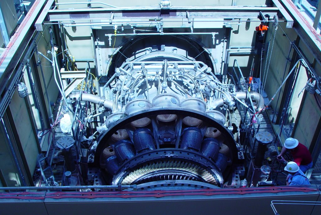
Above is a GE industrial turbine. Note that it is quite large and heavy, and how thick the casing is (bolting for the joints is near the bottom of the photo). Clearly this could never be mounted to an aircraft wing! The air intake is at the far end of the photo, while the exhaust is closest. The mass of smaller pipes is for fuel delivery to the combustors (which have been removed in this photo).

The turbine rotating blades are clearly visible in this picture. The first stage blades are exposed to very corrosive, very high temperature exhaust gas, and are ceramic coated to extend longevity - thus the yellow-ish color. Increasing firing temperatures increases the efficiency of the machines, so there is ongoing research to improve turbine blades. Although it cannot be seen in this photo, the compressor and turbine blades are all mounted on a single shaft that extends throughout the machine.


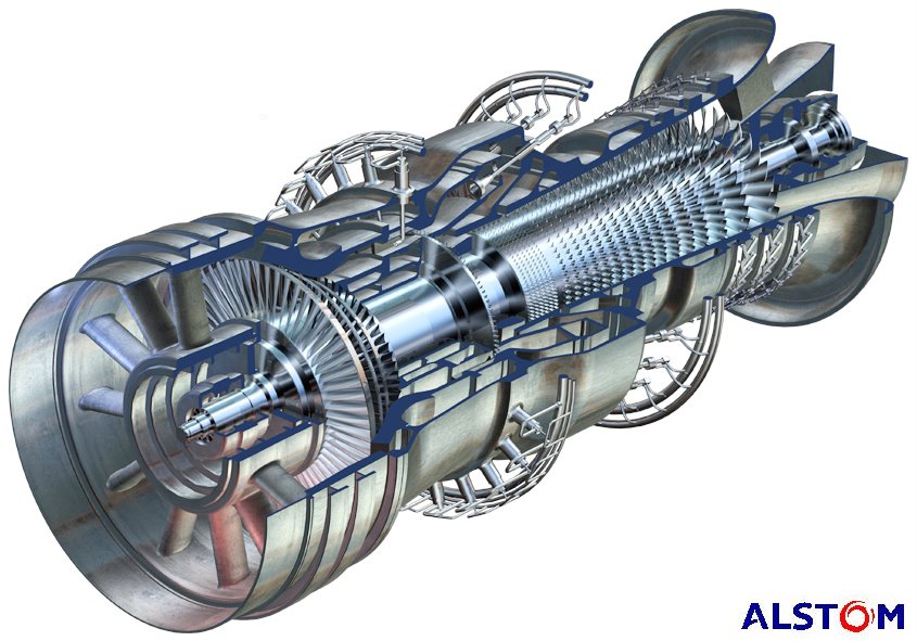
Above is a cut-away drawing of an Alstom industrial turbine. In this rendering, the exhaust is closest to the viewer, and with the cut-away, it is easy to see that the compressor and turbine blades are mounted on a common shaft. Air is drawn in at the far end, compressed, mixed with fuel and burned, and exhausted through the turbine.

This model is unique in that there are two combustion sections. The primary burn section is where the fuel nozzles enter at an angle. The exhaust gases pass through a single stage of turbine blades, then additional fuel is added and burned, and expanded through four more turbine stages. Theoretically in this manner firing temperatures can be reduced.


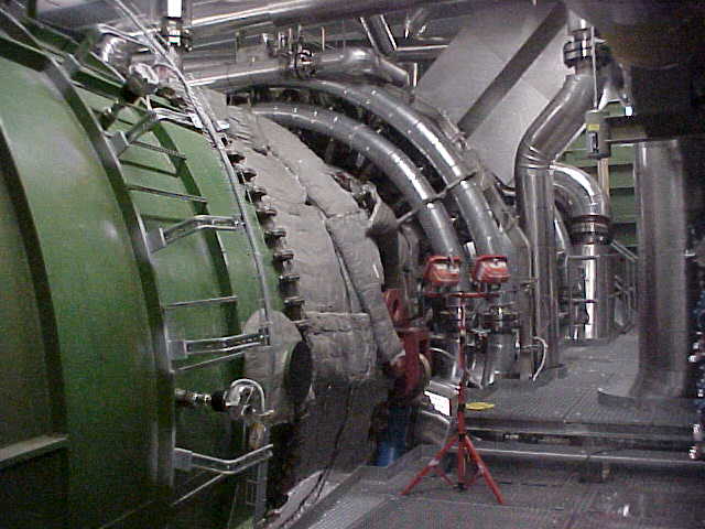
Here is a photo of the above machine.


The same machine, from the other side.


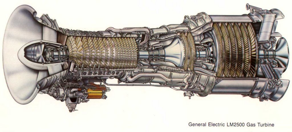
Lastly, here is an example of a commonly used aeroderivative gas turbine,the GE LM2500.
The air inlet is to the left. Air is compressed, fuel added and burned, which turns *two* turbines. This is a two-shaft machine. The first turbine is the high-speed turbine (two stages), which turns the compressor at about 9500 RPM.

The gas is not finished expanding however. It now passes to the second turbine - the power turbine. This second turbine is on a different shaft, rotating at 3600 RPM, which is coupled to an external generator (not shown). The technical term for this is "aerodynamic coupling". Basically the wind exiting the first turbine turns the second turbine.