Search This Blog

Sunday, June 25, 2006

Burning down the house

Gas pipeline rupture and fire in Texas. It happened just outside a power plant, on the fuel gas supply pipeline. The stacks can be seen just to the right of the fireball. Click any photo to enlarge


Aftermath. Amazingly no loss of life and only minor injuries occurred.


Cooling tower destroyed. Center of the blaze was apparently just off the frame to the right.

A cool Ducati GP moto shot

Stuff happens...

The previous post was about photos I've gathered of power plant damage due to accidents.  Here are a few more.

Bad day at the power plant

I've had the good fortune to avoid involvement in accidents involving serious injury or fatalities, although I've lost some friends and acquaintances. The energies involved in electrical generation are almost incomprehensible when they are uncontrolled. Here are a few pictures I've acquired over the years.

Wednesday, June 21, 2006

Aircraft engine failure

What happens when a aero unit turbine wheel fails.
1230 PM, Friday, June 2, 2006 at LAX. XXX Airlines Boeing
767 doing a high power engine run had a #1 engine HPT (high pressure turbine) failure.

The HPT (High Pressure Turbine) failed catastrophically and punctured left wing, #2 engine, peppered the fuselage, and set fire to the aircraft. The turbine disk exited the engine,
sliced through the aircraft belly, and lodged in the outboard
side of the #2 engine. (on the opposite wing of the aircraft)

Choose your seats accordingly :)

Update:  Apparently the HP Turbine disks, which were forged from titanium alloy, had incorrect percentages of the alloy materials.  This allowed stress cracks to form on the disks, which of course failed under high stress.

Below, part of the failed HP turbine disk, lodged in the engine on the opposite wing of the aircraft.


Same description, different angle.


Damage to the aircraft skin.  No surprises here - it's basically thick aluminum foil.


Below, the engine that suffered the failure.  The compressor section is to the right.  The failed disk split the compressor and turbine sections, and of course severed oil and fuel systems.  Flame escaped the turbine and the compressor fed the fire with plenty of air.  Not sure if the fire supression system was damaged also.


Close-up of the damaged section.


Fire damage aft of the engine.


Scorched paint on the fuselage.


Damaged engine cowling.

Wednesday, June 14, 2006

Weight lifting

The blog description says that I'm interested in weight-lifting. That's true. I've also been on a hiatus from exercising since before I started this blog. Part of the reason is work related, and part of it is personal. Now however, I'm trying to get back on track by eating correctly and exercising consistently. So for the past three days I've been hitting it - and have the sore muscles to prove it!

Anyhow here's my routine, for those with interest:

Day 1
Back, Chest, Abs, Cardio

Day 2
Legs and Butt

Day 3
Delts, Abs, Cardio

Day 4
Arms

Day 5 Rest

Repeat ad infinitum.

The eventual goal is to get big and ripped - although it's unlikely as I have the physique of a Kenyan marathon runner (with none of the stamina). So I'll probably have to settle for muscular and fit. Anyway, I'm eating high quality carbs again and very high protein. Time to go do some stair-climbing!

Monday, June 05, 2006

JT8D turbofan


This is a cutaway of the impressive Pratt-Whitney JT8D turbofan. It's an aeroderivative engine used in peaking power plants, and the main competition to the GE LM2500.


A photo of the inlet end.

These are the engines I alluded to in a previous post that actually produce thrust (actually expanding hot gas) in a power plant environment, rather than shaft output. The engine rests on a stand, with the inlet connected to an air filter by ductwork. The exhaust is directed into a turbo-expander (not unlike a water-wheel arrangement) that converts the expanding gas into rotating energy, with the shaft perpendicular to the direction of thrust. Impressive fact: A single low-bypass aircraft engine can provide about 23 Megawatts of electricity.

Aeroderivative engines are high-maintenance. They are frequently changed out when parts fail on them.

The advantage of this arrangement over the LM2500 is that no alignment is required. The fuel lines, instrumentation and duct work are removed, and the engine can be pulled. Replacement is the reverse. The LM2500 must be carefully aligned with the generator shaft in addition to all of the above items. It lengthens the downtime when failure occurs.

Below:  JT8D installation.  Looking at the exhaust into the turboexpander.

I have not operated these type plants much at all, but according to co-workers, the JT8D can handle a compressor stall better than the GE machines as well.

Here's a photo of a dual JT8D installation:

Fascinating early jet engine


I lifted the photo from Wiki, along with the explanation. I'll turn it over to the original author:

"One problem with these early designs, which are called centrifugal-flow engines, was that the compressor worked by "throwing" (accelerating) air outward from the central intake to the outer periphery of the engine, where the air was then compressed by a divergent duct setup, converting its velocity into pressure. An advantage of this design was that it was already well understood, having been implemented in centrifugal superchargers. However, given the early technological limitations on the shaft speed of the engine, the compressor needed to have a very large diameter to produce the power required. A further disadvantage was that the air flow had to be "bent" to flow rearwards through the combustion section and to the turbine and tailpipe.

Austrian Anselm Franz of Junkers' engine division (Junkers Motoren or Jumo) addressed these problems with the introduction of the axial-flow compressor. Essentially, this is a turbine in reverse. Air coming in the front of the engine is blown towards the rear of the engine by a fan stage (convergent ducts), where it is crushed against a set of non-rotating blades called stators (divergent ducts). The process is nowhere near as powerful as the centrifugal compressor, so a number of these pairs of fans and stators are placed in series to get the needed compression. Even with all the added complexity, the resulting engine is much smaller in diameter."

It's impressive that a single stage centrifugal compressor could accomplish the necessary compression to produce enough thrust to fly an aircraft. Then too I've seen home-made turbocharger conversions to turbine engines. They aren't quite this level of sophistication though! :)

Anyway, it's a cool cutaway and I wanted to share it.

Saturday, June 03, 2006

Gas turbine cut-aways and photos

Here are a few cutaways and photos of gas turbines.

(Click on any image to enlarge)

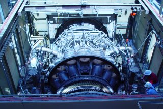
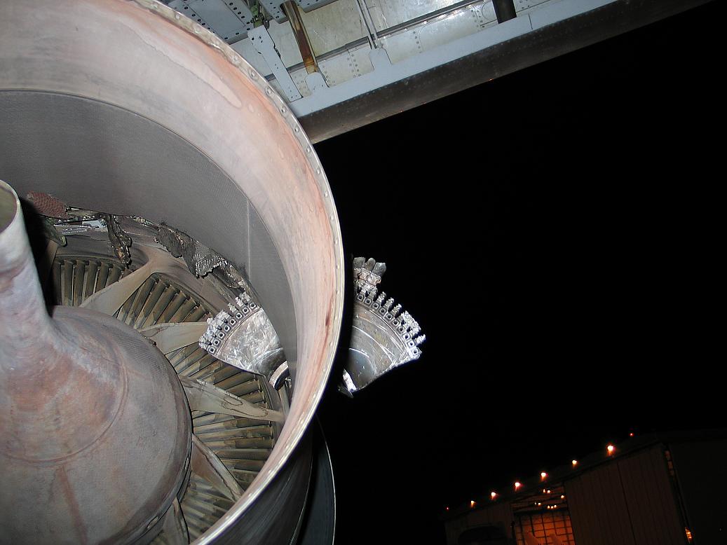
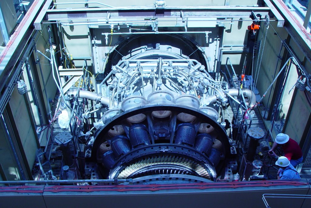
Above is a GE industrial turbine. Note that it is quite large and heavy, and how thick the casing is (bolting for the joints is near the bottom of the photo). Clearly this could never be mounted to an aircraft wing! The air intake is at the far end of the photo, while the exhaust is closest. The mass of smaller pipes is for fuel delivery to the combustors (which have been removed in this photo).

The turbine rotating blades are clearly visible in this picture. The first stage blades are exposed to very corrosive, very high temperature exhaust gas, and are ceramic coated to extend longevity - thus the yellow-ish color. Increasing firing temperatures increases the efficiency of the machines, so there is ongoing research to improve turbine blades. Although it cannot be seen in this photo, the compressor and turbine blades are all mounted on a single shaft that extends throughout the machine.


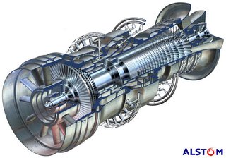
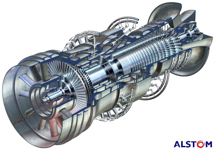
Above is a cut-away drawing of an Alstom industrial turbine. In this rendering, the exhaust is closest to the viewer, and with the cut-away, it is easy to see that the compressor and turbine blades are mounted on a common shaft. Air is drawn in at the far end, compressed, mixed with fuel and burned, and exhausted through the turbine.

This model is unique in that there are two combustion sections. The primary burn section is where the fuel nozzles enter at an angle. The exhaust gases pass through a single stage of turbine blades, then additional fuel is added and burned, and expanded through four more turbine stages. Theoretically in this manner firing temperatures can be reduced.


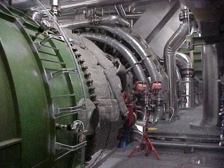
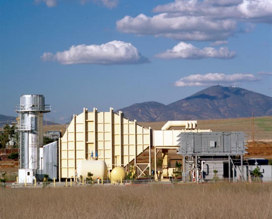
Here is a photo of the above machine.


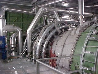
The same machine, from the other side.


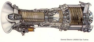
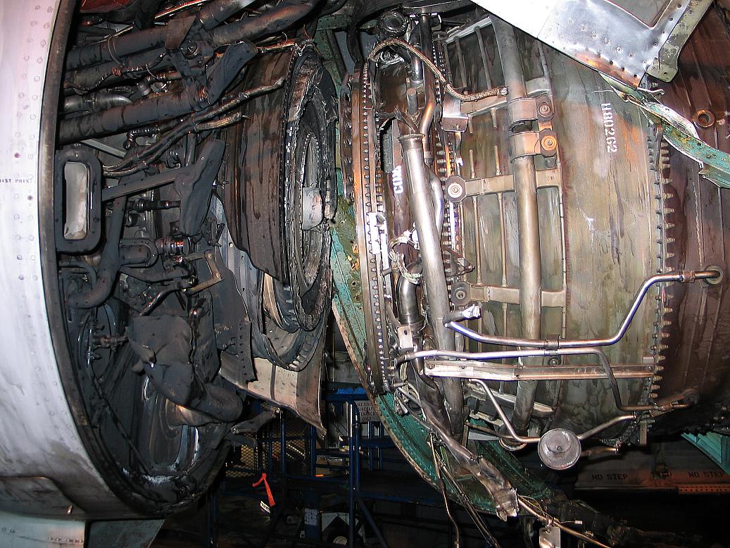
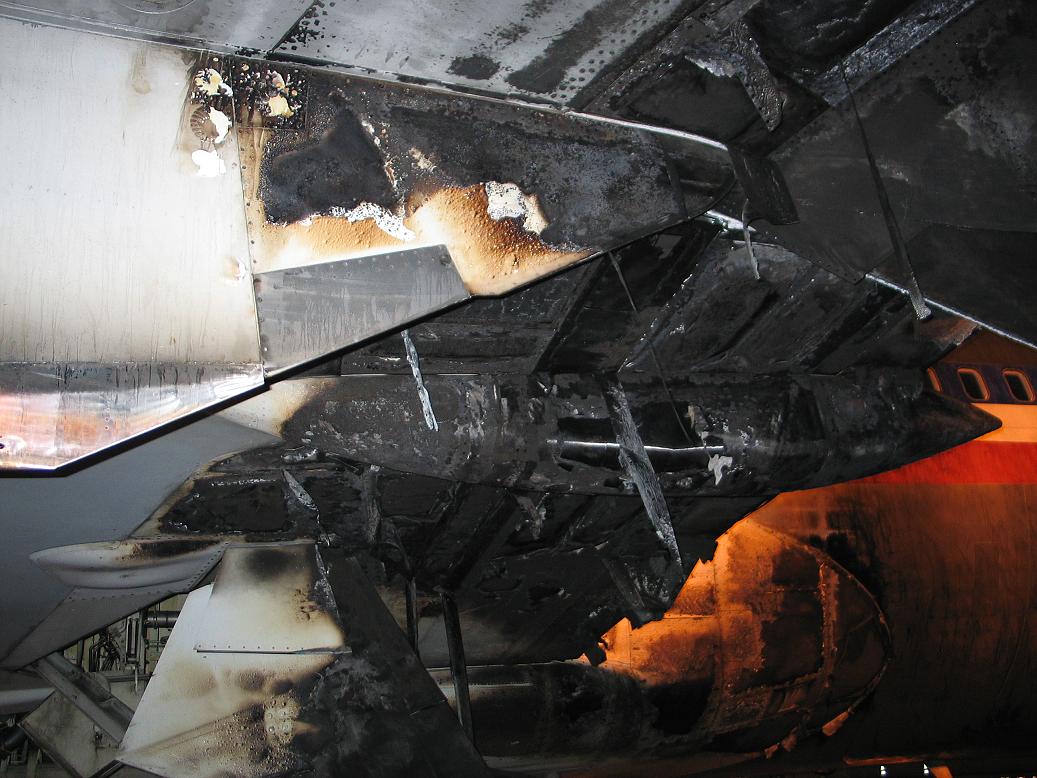
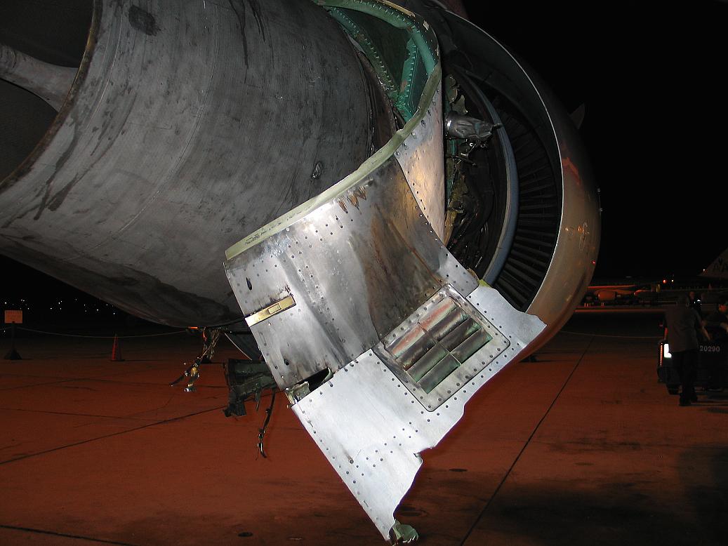
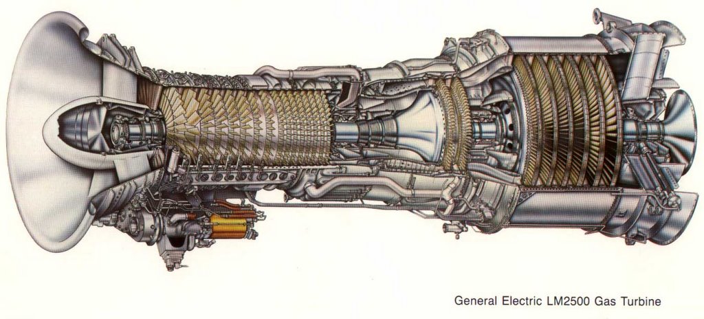
Lastly, here is an example of a commonly used aeroderivative gas turbine,the GE LM2500.
The air inlet is to the left. Air is compressed, fuel added and burned, which turns *two* turbines. This is a two-shaft machine. The first turbine is the high-speed turbine (two stages), which turns the compressor at about 9500 RPM.

The gas is not finished expanding however. It now passes to the second turbine - the power turbine. This second turbine is on a different shaft, rotating at 3600 RPM, which is coupled to an external generator (not shown). The technical term for this is "aerodynamic coupling". Basically the wind exiting the first turbine turns the second turbine.