(Click on any image to enlarge)
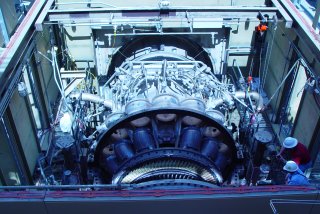
Above is a GE industrial turbine. Note that it is quite large and heavy, and how thick the casing is (bolting for the joints is near the bottom of the photo). Clearly this could never be mounted to an aircraft wing! The air intake is at the far end of the photo, while the exhaust is closest. The mass of smaller pipes is for fuel delivery to the combustors (which have been removed in this photo).
The turbine rotating blades are clearly visible in this picture. The first stage blades are exposed to very corrosive, very high temperature exhaust gas, and are ceramic coated to extend longevity - thus the yellow-ish color. Increasing firing temperatures increases the efficiency of the machines, so there is ongoing research to improve turbine blades. Although it cannot be seen in this photo, the compressor and turbine blades are all mounted on a single shaft that extends throughout the machine.
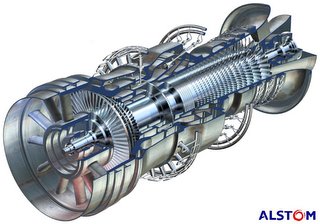
Above is a cut-away drawing of an Alstom industrial turbine. In this rendering, the exhaust is closest to the viewer, and with the cut-away, it is easy to see that the compressor and turbine blades are mounted on a common shaft. Air is drawn in at the far end, compressed, mixed with fuel and burned, and exhausted through the turbine.
This model is unique in that there are two combustion sections. The primary burn section is where the fuel nozzles enter at an angle. The exhaust gases pass through a single stage of turbine blades, then additional fuel is added and burned, and expanded through four more turbine stages. Theoretically in this manner firing temperatures can be reduced.
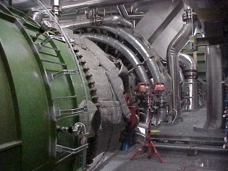
Here is a photo of the above machine.
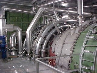
The same machine, from the other side.
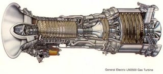
Lastly, here is an example of a commonly used aeroderivative gas turbine,the GE LM2500.
The air inlet is to the left. Air is compressed, fuel added and burned, which turns *two* turbines. This is a two-shaft machine. The first turbine is the high-speed turbine (two stages), which turns the compressor at about 9500 RPM.
The gas is not finished expanding however. It now passes to the second turbine - the power turbine. This second turbine is on a different shaft, rotating at 3600 RPM, which is coupled to an external generator (not shown). The technical term for this is "aerodynamic coupling". Basically the wind exiting the first turbine turns the second turbine.

No comments:
Post a Comment