
"'Misinformation' and 'disinformation are just different words for wrong-think" - Unknown
A few pictures for now.
Below: Preparing to remove the High Pressure (HP) steam turbine rotor

Below: Using a Faro arm to measure diaphragm dishing. It's connected to a laptop that models what a flat surface would look like, then compares that to how bent the diaphragm is, and by how much.


Cutaway of the steam turbine generator stator bar, showing individual braids.

Below: Pallets of big turbine shell bolts that need to be cleaned up

Below: Pulling out the first of the old stator bars after the wedges have been removed.

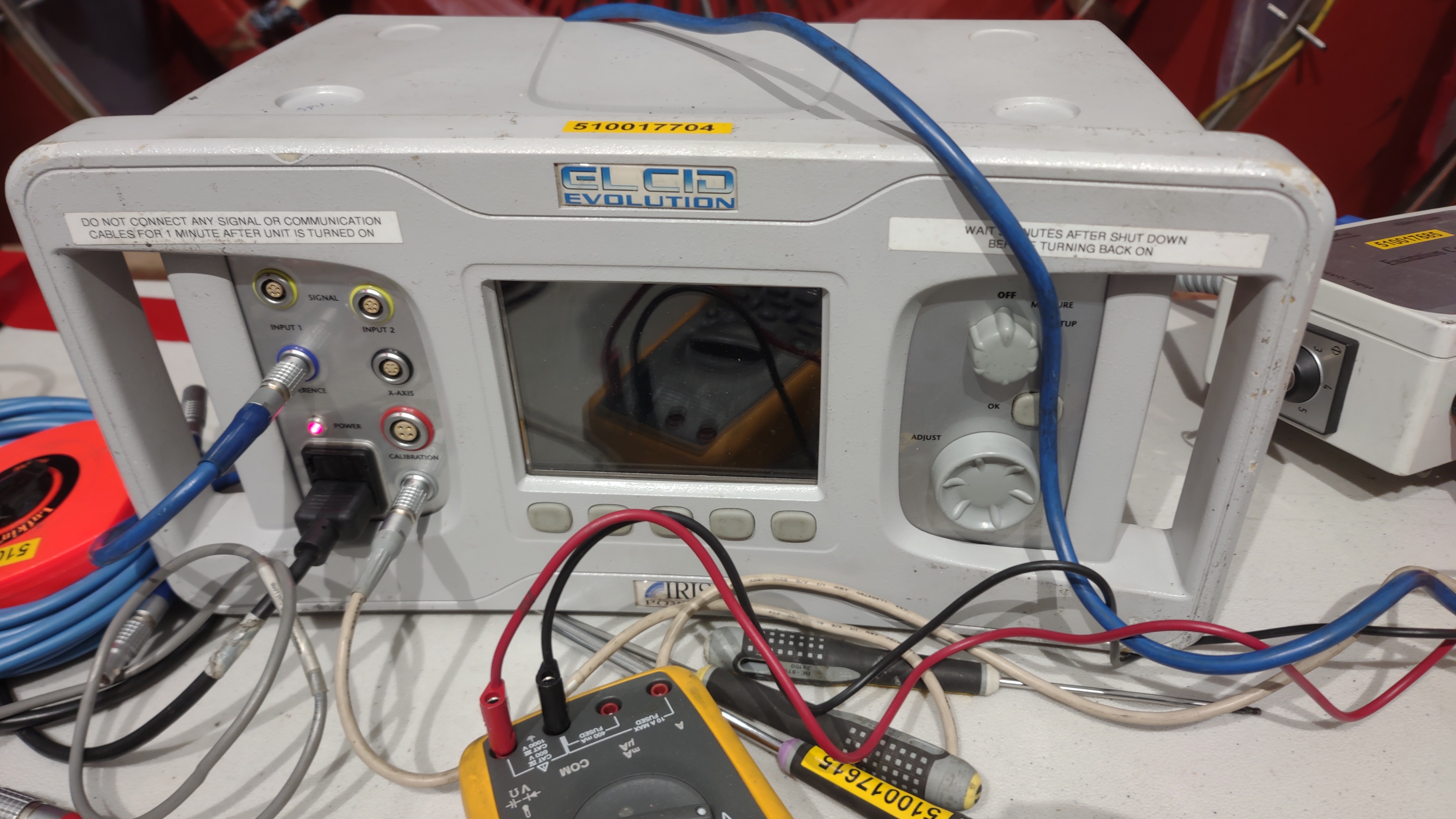
Below: Performing an EL CID test on the core iron following bar removal. This test looks for shorting between the steel laminations that the core is built from.

Below: Diaphragm racks

Below: Casing repairs at the horizontal joint where steam cutting had occurred

Below: The edge of the generator core iron, called "Step Iron". You can see the individual laminations that the core is made from. Each of these must be electrically insulated from the other laminations. This is what the EL CID test checks - that the individual steel laminations are not shorted together.

Below: Fluorescent dye penetrant checking for cracks in the turbine rotor blades. The dye will be wiped off, then it will weep into any cracks and they will show under UV light.

Various electrical breakers under clearance in the 480 volt motor control center (MCC)


Steam turbine Intermediate pressure and Low pressure (IP/LP) turbine on stands following sand blasting

Below: Steam turbine generator with the outer stator bars installed.

Refilling the steam turbine lube oil tank following filtration in the tanker trailer.

Below: Test fitting repaired diaphragms in the lower HP shell.

Below: Water droplet erosion on the leading edge of one of the last rotating steam turbine blades. At this point in the steam cycle, the steam is already beginning to condense before it exits the steam turbine. Small water droplets that are just beginning to form chew up the blades. This point where the steam begins to condense is sometimes called the "Wilson line", and it's best to have that be in the turbine exhaust plenum or condenser, and not inside the turbine.

Below: Wedging the stator bars in place against immense electrostatic forces they see during operation.

Below: Pieces of the stator bar wedging. The ripple spring gets about halfway compressed.

Below: Bolt world, now occupied by bits and pieces of steam turbine.

Below: Turbine casing, cracked by high pressure steam, now ground out - about to be re-welded.

Below: Diaphragm centering slot. It had been wallowed out, was repaired and re-machined.

Below: Inside one of the tool trailers up on the steam turbine deck. Lots of rigging.

Below: The small electric boiler on site began leaking. Investigation showed it was a hand hole gasket.


The cover plate got a temporary lasso so that it would not fall into the boiler.

Below: A 3D jigsaw puzzle. The end windings of the generator each has a custom-made connector made of brazed-together copper bus bars.


Below: Test fitting a custom-made copper connector.

Below: Digitally measuring the each stator wedge for tightness - they go up and down each row every inch or two with a calibrated tapping device and record how much the wedge ripple spring compresses

Below: Preparing to lift and install the T2 Bearing


Below: Installing the T3 bearing.

Below: T2 Bearing with the upper half removed. Braided wires connect to thermocouple elements that are embedded in the bearing metal

Below: Mesmerizing video of a machine polishing the thrust collars in place on the rotor stand. The machine rotates instead of the item being machined!
Below: Brief video of refilling the turbine lube oil tank.
No comments:
Post a Comment