Search This Blog

Showing posts with label Cutaway. Show all posts

Sunday, October 20, 2013

The reactor with a hole in its head...

In 2002 the US came very close to having a massive loss of coolant accident that probably would have led to major core melting (melt-down), and a release of offsite contamination.  Everyone knows about the meltdown at Three Mile Island, but not many people know about this...

Background:
In a Pressurized Water Reactor (PWR), the control rods are completely removed from the core after the reactor is up to full power, and dilute Boric Acid (a strong neutron poison) is carefully added to control reactivity.  

The purpose of this process is to achieve a flatter neutron flux profile throughout the core. 

A flat neutron flux is desirable for a couple of reasons:  It helps to even out fuel burnup and it helps to reduce hot and cold coolant channels.  When control rods are partially inserted into an operating reactor core, neutron flux is depressed near them, since they absorb neutrons.  Therefore fewer fissions occur near the control rods.  This localized reduction of fission causes uneven fuel burn and creates cold zones due to reduced fission near the rods.  For a given power output, other sections of the reactor core away from the control rods must now run hotter to compensate.

Below, a side-view of a reactor core.  The solid line indicates neutron population in this reactor at steady-state power, with a control rod partially inserted to control reactor power.  Because there are very few neutrons in the area adjacent to the control rod, for a given power level, other areas of the core have to produce more fissions.  The spots on the solid line marked "A" are those places where we might see excessive fissions, overheating, and possible fuel element failures.

The dashed line indicates neutron population with the control rod removed (which is possible if you add Boric Acid as a virtual liquid control rod).  As you can see, neutron population is more consistent throughout the reactor, and therefore there won't be any excessive localized fission and heating, as you see at the points marked "A"


With borated primary coolant, neutrons are depressed equally throughout the core, and so power generation is more evenly distributed, and the reactor can be run closer to its thermal limit, because there is no need to account for hot and cold zones due to tilting of the neutron flux.

However you would hope that there is a better way to keep a flat neutron flux profile throughout a reactor core than using very hot diluted boric acid in the primary coolant loop.

As mentioned above, the primary coolant in these PWR reactors contains Boric Acid, which is a mild acid.  For this reason, the piping, pumps, valves, etc are all made of high chrome steel (stainless steel).

The reactor vessel and closure head, however, are not.  Due to their size, it is impractical to make the entire thing from stainless steel.  Instead, the reactor vessel and head are made from carbon steel, and their interior is clad with a sheet of 3/8" thick stainless steel.  In this way, the carbon steel, which is not resistant to acids, is protected from contact with the Boric Acid in the primary coolant.
 
The Event:
In 2002, Davis-Besse nuclear power plant in Ohio discovered they had a very minor primary coolant leak. The coolant was leaking out along a penetration in the reactor vessel head, where a Control Rod Drive Mechanism (CRDM) was mounted.  The CRDM is what pulls the control rods out of the core and allows the reactor to start and shut down.  The coolant leak was so minor that it hadn't been noticed - in a million gallon system, a minor leak can go undetected almost forever.  Any water leaking from the primary coolant would also be quite hot and would flash to steam immediately, so no water puddling would occur.


Davis-Besse had a tiny coolant leak, however.  One which they were unaware of.  In 2002 the plant shut down for a refueling outage, and performed an inspection underneath the insulation on the reactor vessel head.  This was done after other plants of the same design had uncovered minor leakage.  They found a little problem...

At the time it was discovered, the acid had eaten away a hole the size of a football completely through the reactor vessel head in the area of the leaking CRDM penetration.  The only thing that was holding the 2500 psig primary coolant in place was 3/8" of stainless steel cladding, which was bulging outwards from the pressure. 

Below is a picture of a Babcock & Wilcox design PWR primary coolant loop, with the reactor vessel head highlighted.

 Below is a cut-away of a B&W reactor vessel head, with a zoom-in on the point of the leak.

Below are images of the hole in the reactor vessel head.

The photo below gives you an idea how thick engineers designed the reactor vessel head to keep 2500 psig of primary coolant in place.  It's astonishing (and wonderful) that thin piece of 3/8" of stainless steel was able to keep the coolant from blasting out.

This would not have been merely a primary coolant leak.  This would have been a major accident.  Here are some of the potential consequences of such a massive leak, had the cladding ruptured:
  1. A massive steam/water jet would have blasted out of this hole, certainly damaging this control rod, but possibly adjacent ones also.  Could the ability of the reactor to shut down been compromised?
  2. The steam/water blast probably would have ripped tons of insulation loose.  This would have fouled the intake of the emergency water re-injection system, which takes suction from the floor of the containment building.
  3. Major coolant leak accidents are typically modeled for weaker points in the primary coolant system - pumps, steam generators, drain lines, etc.  These are equipped with remote-operated valves to isolate these leaks from the reactor core.  This leak was was directly above the reactor core, and not isolable from it.  Continuous water injection directly into the core would be required for several months to prevent decay heat from melting it.
  4. It is very likely that with the reactor fill system compromised due to ingesting insulation, and an unisolable leak right above the fuel, that core damage would have occurred.
In the end it took a couple of years to manufacture a replacement head and get the plant back online.  

Saturday, June 22, 2013

Steam Power and Electricity - Dynamos

Steam engines were invented around 1700 AD.  Using a steam engine to turn a generator in order to make electricity would have to wait for another 130 years.  Electricity was not understood, and the earliest generators used electrostatic principles to push electrons around.  Surviving examples of these static-electricity type generators include the Wimshurst generator and the Van de Graaf generator.

Saturday, May 25, 2013

Early Steam Turbines

Today those of us who work with steam turbines for a living are familiar with axial-flow turbines, where steam flows through a series of rotating and stationary blades in a direction along the shaft.  Below is a cutaway of a small five stage turbine. 

Tuesday, April 02, 2013

Another Gas Turbine Cutaway

Since the Gas Turbine Cutaway post appears to be one of the most-viewed on the blog, here's another one.  This is a really odd design that Alstom came up with back in the 1980s. 

It's a pretty cool design, and it kind of reminds me of a model airplane engine.  This is the Alstom GT11N.  I think it puts out about 100 Megawatts.  What's interesting about this design is that combustion occurs outside of the turbine proper, in a "silo combustor". 

Air is drawn in at the right side in this picture, compressed in several stages, and then it flows up just inside the wall of the the large cylinder at the center.  This pre-heats the combustion air while keeping the inner combustion liner cool and preventing it from melting.  The air is blended with natural gas (or fuel oil) at the top of the silo combustor.  The fuel/air mixture is burned as it travels down in the silo, then the hot gases are routed into a donut called the hot gas casingthat spreads them all around the turbine shaft, where they are allowed to expand and drive the turbine.


Here is another picture (actually an advertisement) that shows some of the parts in the gas flowpath.
I don't know much more about this machine than this.  It doesn't appear to have been too successful commercially, because there isn't much on the web about them, and the axial combustion scheme appears to be the dominant technology.  Still, I thought this was a cool idea...


Monday, June 05, 2006

JT8D turbofan


This is a cutaway of the impressive Pratt-Whitney JT8D turbofan. It's an aeroderivative engine used in peaking power plants, and the main competition to the GE LM2500.


A photo of the inlet end.

These are the engines I alluded to in a previous post that actually produce thrust (actually expanding hot gas) in a power plant environment, rather than shaft output. The engine rests on a stand, with the inlet connected to an air filter by ductwork. The exhaust is directed into a turbo-expander (not unlike a water-wheel arrangement) that converts the expanding gas into rotating energy, with the shaft perpendicular to the direction of thrust. Impressive fact: A single low-bypass aircraft engine can provide about 23 Megawatts of electricity.

Aeroderivative engines are high-maintenance. They are frequently changed out when parts fail on them.

The advantage of this arrangement over the LM2500 is that no alignment is required. The fuel lines, instrumentation and duct work are removed, and the engine can be pulled. Replacement is the reverse. The LM2500 must be carefully aligned with the generator shaft in addition to all of the above items. It lengthens the downtime when failure occurs.

Below:  JT8D installation.  Looking at the exhaust into the turboexpander.

I have not operated these type plants much at all, but according to co-workers, the JT8D can handle a compressor stall better than the GE machines as well.

Here's a photo of a dual JT8D installation:

Fascinating early jet engine


I lifted the photo from Wiki, along with the explanation. I'll turn it over to the original author:

"One problem with these early designs, which are called centrifugal-flow engines, was that the compressor worked by "throwing" (accelerating) air outward from the central intake to the outer periphery of the engine, where the air was then compressed by a divergent duct setup, converting its velocity into pressure. An advantage of this design was that it was already well understood, having been implemented in centrifugal superchargers. However, given the early technological limitations on the shaft speed of the engine, the compressor needed to have a very large diameter to produce the power required. A further disadvantage was that the air flow had to be "bent" to flow rearwards through the combustion section and to the turbine and tailpipe.

Austrian Anselm Franz of Junkers' engine division (Junkers Motoren or Jumo) addressed these problems with the introduction of the axial-flow compressor. Essentially, this is a turbine in reverse. Air coming in the front of the engine is blown towards the rear of the engine by a fan stage (convergent ducts), where it is crushed against a set of non-rotating blades called stators (divergent ducts). The process is nowhere near as powerful as the centrifugal compressor, so a number of these pairs of fans and stators are placed in series to get the needed compression. Even with all the added complexity, the resulting engine is much smaller in diameter."

It's impressive that a single stage centrifugal compressor could accomplish the necessary compression to produce enough thrust to fly an aircraft. Then too I've seen home-made turbocharger conversions to turbine engines. They aren't quite this level of sophistication though! :)

Anyway, it's a cool cutaway and I wanted to share it.

Saturday, June 03, 2006

Gas turbine cut-aways and photos

Here are a few cutaways and photos of gas turbines.

(Click on any image to enlarge)

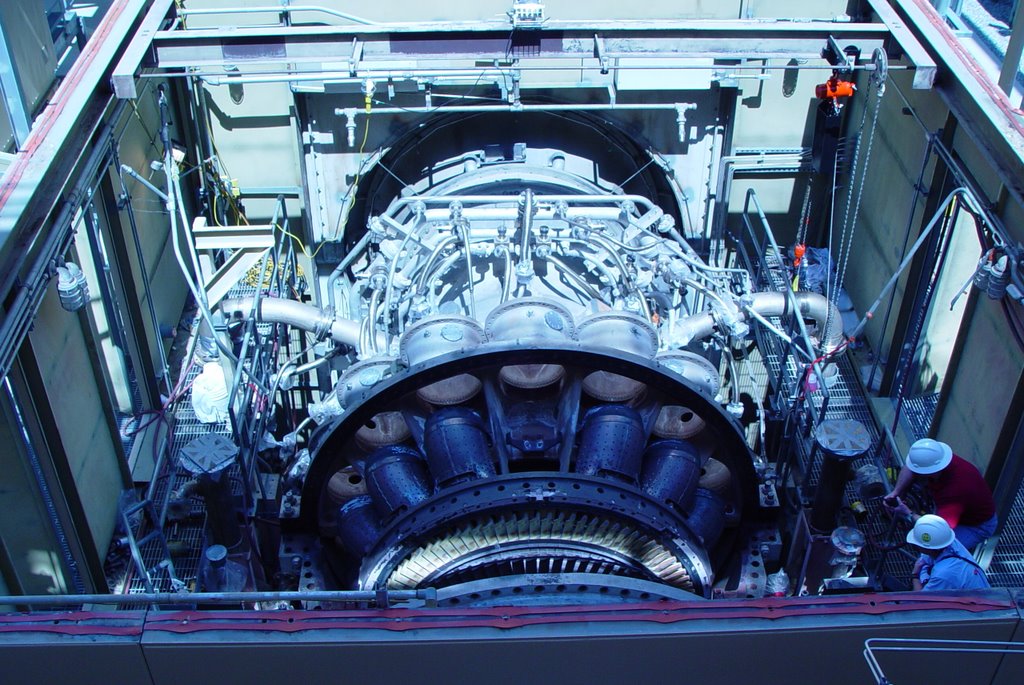
Above is a GE industrial turbine. Note that it is quite large and heavy, and how thick the casing is (bolting for the joints is near the bottom of the photo). Clearly this could never be mounted to an aircraft wing! The air intake is at the far end of the photo, while the exhaust is closest. The mass of smaller pipes is for fuel delivery to the combustors (which have been removed in this photo).

The turbine rotating blades are clearly visible in this picture. The first stage blades are exposed to very corrosive, very high temperature exhaust gas, and are ceramic coated to extend longevity - thus the yellow-ish color. Increasing firing temperatures increases the efficiency of the machines, so there is ongoing research to improve turbine blades. Although it cannot be seen in this photo, the compressor and turbine blades are all mounted on a single shaft that extends throughout the machine.


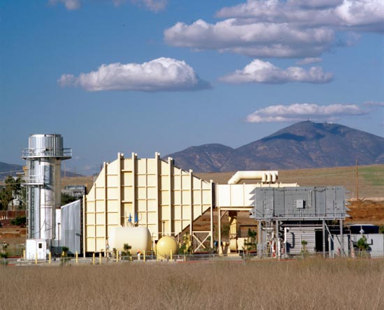
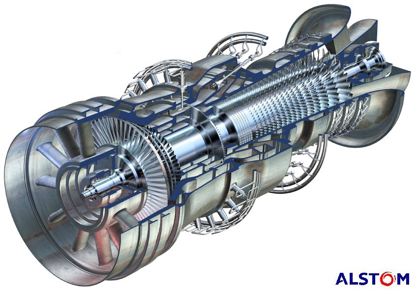
Above is a cut-away drawing of an Alstom industrial turbine. In this rendering, the exhaust is closest to the viewer, and with the cut-away, it is easy to see that the compressor and turbine blades are mounted on a common shaft. Air is drawn in at the far end, compressed, mixed with fuel and burned, and exhausted through the turbine.

This model is unique in that there are two combustion sections. The primary burn section is where the fuel nozzles enter at an angle. The exhaust gases pass through a single stage of turbine blades, then additional fuel is added and burned, and expanded through four more turbine stages. Theoretically in this manner firing temperatures can be reduced.


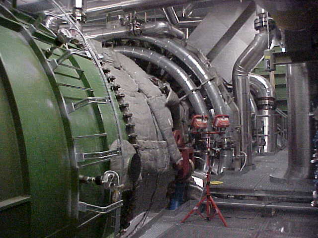
Here is a photo of the above machine.


The same machine, from the other side.


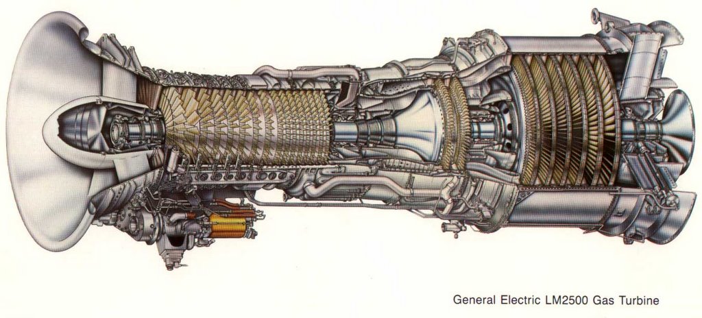
Lastly, here is an example of a commonly used aeroderivative gas turbine,the GE LM2500.
The air inlet is to the left. Air is compressed, fuel added and burned, which turns *two* turbines. This is a two-shaft machine. The first turbine is the high-speed turbine (two stages), which turns the compressor at about 9500 RPM.

The gas is not finished expanding however. It now passes to the second turbine - the power turbine. This second turbine is on a different shaft, rotating at 3600 RPM, which is coupled to an external generator (not shown). The technical term for this is "aerodynamic coupling". Basically the wind exiting the first turbine turns the second turbine.