"Never value the advantages derived from anything involving breach of faith, loss of self-respect, hatred, suspicion, or execration of others, of insincerity or the desire for something which has to be veiled or hidden." - Marcus Aurelius

An advertisement-free blog about motorcycling, Northern life, home improvement, power plants, submarines, nuclear stuff, and a few other off-beat subjects. Comments are welcome. (Image is the Selway Crags in Northern Idaho)
Showing posts with label aeroderivative. Show all posts
Showing posts with label aeroderivative. Show all posts
Sunday, January 23, 2022
Compressor Stall on Industrial Turbines


Wednesday, June 21, 2006
Aircraft engine failure
What happens when a aero unit turbine wheel fails.
1230 PM, Friday, June 2, 2006 at LAX. XXX Airlines Boeing
767 doing a high power engine run had a #1 engine HPT (high pressure turbine) failure.
The HPT (High Pressure Turbine) failed catastrophically and punctured left wing, #2 engine, peppered the fuselage, and set fire to the aircraft. The turbine disk exited the engine,
sliced through the aircraft belly, and lodged in the outboard
side of the #2 engine. (on the opposite wing of the aircraft)
Choose your seats accordingly :)
Update: Apparently the HP Turbine disks, which were forged from titanium alloy, had incorrect percentages of the alloy materials. This allowed stress cracks to form on the disks, which of course failed under high stress.
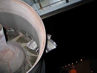
Below, part of the failed HP turbine disk, lodged in the engine on the opposite wing of the aircraft.
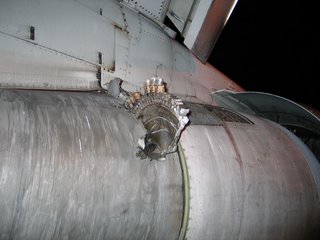
Same description, different angle.
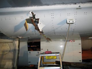
Damage to the aircraft skin. No surprises here - it's basically thick aluminum foil.
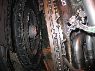
Below, the engine that suffered the failure. The compressor section is to the right. The failed disk split the compressor and turbine sections, and of course severed oil and fuel systems. Flame escaped the turbine and the compressor fed the fire with plenty of air. Not sure if the fire supression system was damaged also.
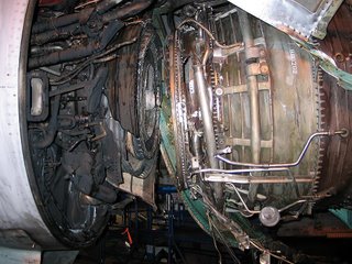
Close-up of the damaged section.
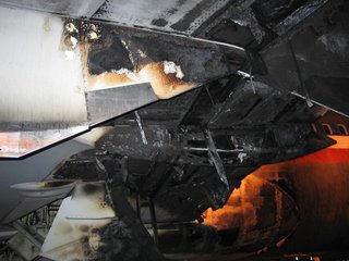
Fire damage aft of the engine.
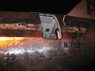
Scorched paint on the fuselage.
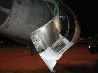
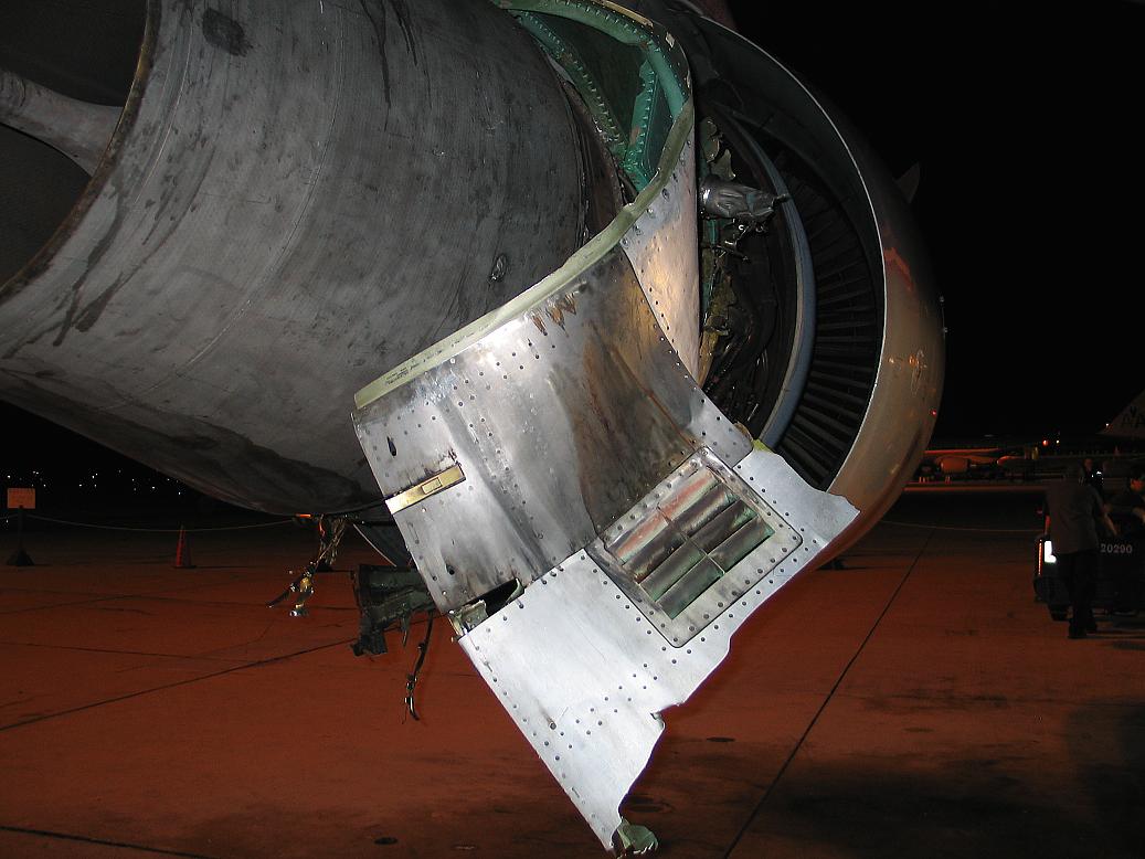
Damaged engine cowling.
1230 PM, Friday, June 2, 2006 at LAX. XXX Airlines Boeing
767 doing a high power engine run had a #1 engine HPT (high pressure turbine) failure.
The HPT (High Pressure Turbine) failed catastrophically and punctured left wing, #2 engine, peppered the fuselage, and set fire to the aircraft. The turbine disk exited the engine,
sliced through the aircraft belly, and lodged in the outboard
side of the #2 engine. (on the opposite wing of the aircraft)
Choose your seats accordingly :)
Update: Apparently the HP Turbine disks, which were forged from titanium alloy, had incorrect percentages of the alloy materials. This allowed stress cracks to form on the disks, which of course failed under high stress.
Below, part of the failed HP turbine disk, lodged in the engine on the opposite wing of the aircraft.
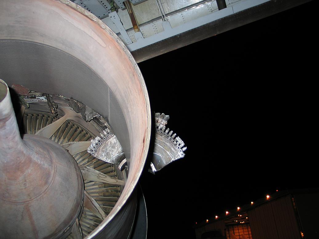
Same description, different angle.

Damage to the aircraft skin. No surprises here - it's basically thick aluminum foil.

Below, the engine that suffered the failure. The compressor section is to the right. The failed disk split the compressor and turbine sections, and of course severed oil and fuel systems. Flame escaped the turbine and the compressor fed the fire with plenty of air. Not sure if the fire supression system was damaged also.
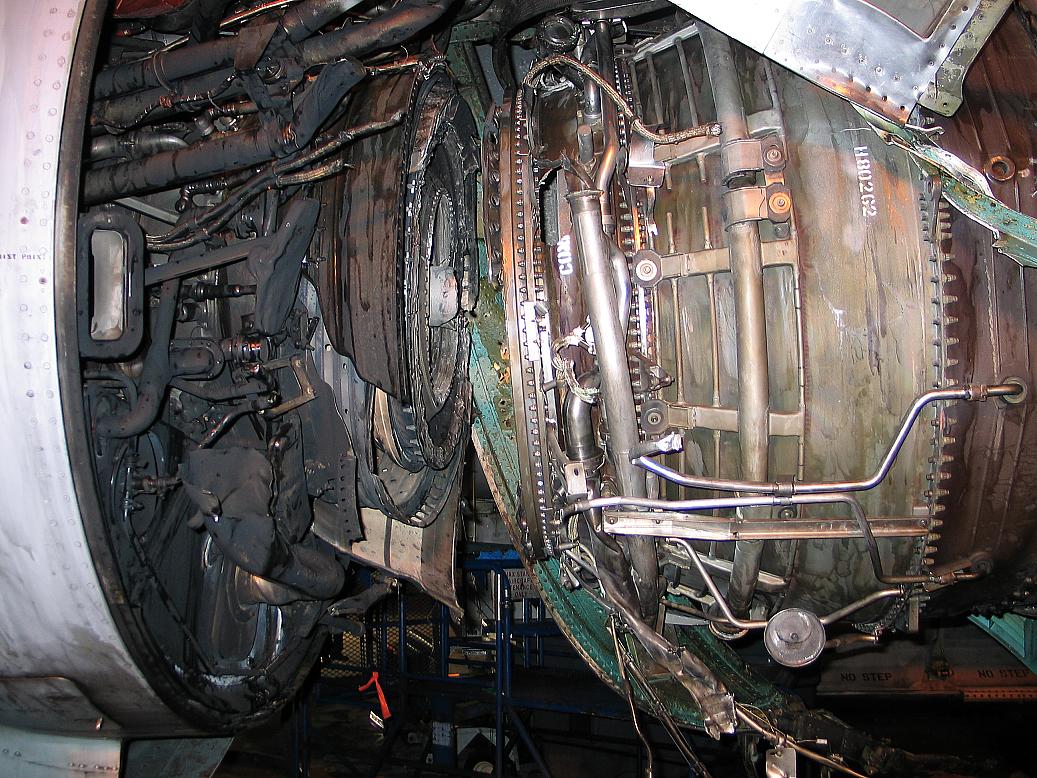
Close-up of the damaged section.
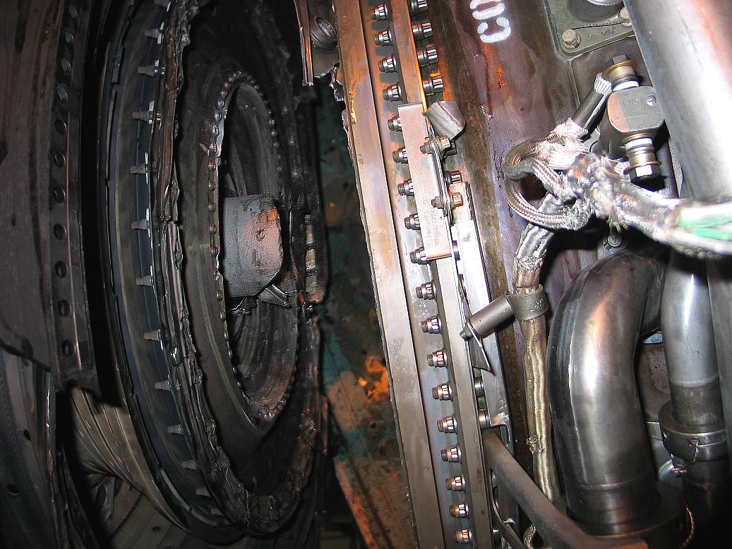
Fire damage aft of the engine.
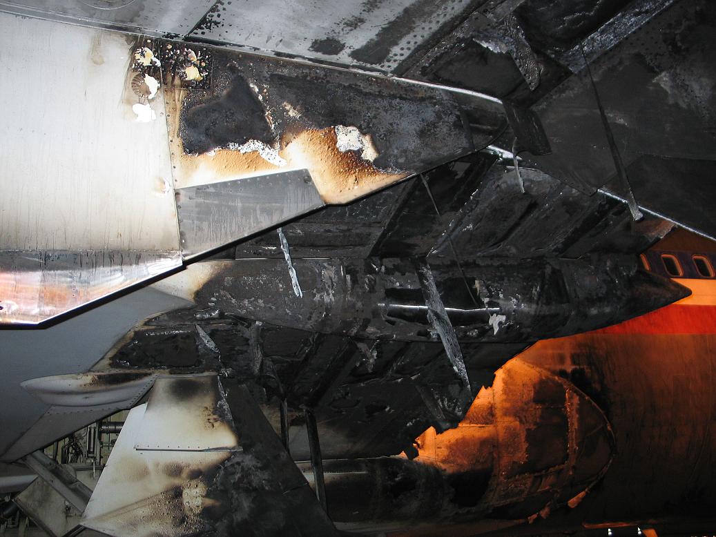
Scorched paint on the fuselage.

Damaged engine cowling.
Monday, June 05, 2006
JT8D turbofan

This is a cutaway of the impressive Pratt-Whitney JT8D turbofan. It's an aeroderivative engine used in peaking power plants, and the main competition to the GE LM2500.

A photo of the inlet end.
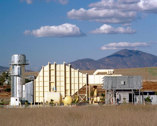
These are the engines I alluded to in a previous post that actually produce thrust (actually expanding hot gas) in a power plant environment, rather than shaft output. The engine rests on a stand, with the inlet connected to an air filter by ductwork. The exhaust is directed into a turbo-expander (not unlike a water-wheel arrangement) that converts the expanding gas into rotating energy, with the shaft perpendicular to the direction of thrust. Impressive fact: A single low-bypass aircraft engine can provide about 23 Megawatts of electricity.
Aeroderivative engines are high-maintenance. They are frequently changed out when parts fail on them.
The advantage of this arrangement over the LM2500 is that no alignment is required. The fuel lines, instrumentation and duct work are removed, and the engine can be pulled. Replacement is the reverse. The LM2500 must be carefully aligned with the generator shaft in addition to all of the above items. It lengthens the downtime when failure occurs.
Below: JT8D installation. Looking at the exhaust into the turboexpander.

I have not operated these type plants much at all, but according to co-workers, the JT8D can handle a compressor stall better than the GE machines as well.
Here's a photo of a dual JT8D installation:
Monday, May 29, 2006
Entering the jet age
In 2001 I was ready for a change. Many of my co-workers had vacated the coal-fired facility for brand-new gas turbine combined cycle power plants, and I was keen on getting into this exciting technology.
Note – small gas turbine power plants and turbine-powered gas pipeline compressing stations have been around for decades. A government/industry collaboration to advance gas turbine technology bore fruit in the late 1990’s. This started a massive building boom in large, highly efficient gas turbine plants.
I started looking around, and eventually was offered a position at a large (1048 Megawatt) facility that was then under construction. I went from burning dirt to operating one of the newest and most advanced gas turbines on the planet :) Fortunately it wasn't too difficult of a change, and being fully automated, it was not as challenging as the coal-burner to operate. I also learned that while gas turbine combustion and control logic are exceedingly complicated, the principle of operation is ridiculously simple. While the principle has been understood for a long time, it's only since WWII that practical gas turbines were actually built.
So how does a gas turbine work? As with coal furnaces, there are two major types that differ significantly from one another, although they both use the same principle, the Brayton Cycle.
Below is a diagram showing the four stages of combustion, both for a piston engine (the otto cycle) and a gas turbine (the brayton cycle). The similarities are that air is compressed, fuel is added and ignited, and work is derived from the expansion of the heated gases. The difference is that the piston engine delivers intermittent power, while the gas turbine compresses, burns, and delivers power continuously.
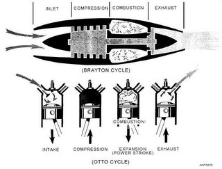
One footnote about the diagram: Most gas turbines used in power generation are not optimized to produce thrust (with one exception that I'm aware of), instead the turbine rotor will have an output shaft that spins at 3600 RPM, turning a generator.
The two types of gas turbines are calle aeroderivative and industrial. It's somewhat self-descriptive, except for the engineering finesse on each design. Aeroderivative engines are gas turbines originally designed for aircraft - they are light, high-revving, easily replaceable machines. In contrast, industrial gas turbines are heavy behemoths that turn at 3600 RPM and are not intended to be removed.
The simpler design, the industrial (or frame) engine, has a single shaft that has an axial compressor at one end, a combustion zone in the center, and a turbine at the exit end. How does it work? The compressor pulls in an enormous mass of filtered air and compresses it. Next, fuel is precisely metered and pre-mixed with the compressed air, and burned in a continuous process. The superheated air expands with great force trough several stages of turbine blades, which convert the expanding gas energy into rotational energy. Because the compressor and turbine are on the same shaft, the turbine provides the energy to drive the compressor, plus has extra power left over to run a generator. The shells on industrial turbines tend to be a couple of inches thick, so that a catastrophic failure will typically be contained within the shell.
In the aeroderivative design there are two rotors. One rotor is high-speed, typically operating at 9500-9700 RPM. This section contains the compressor, combustion zone and a high speed turbine to drive the compressor. In the exhaust path right behind the high speed turbine is a 'power turbine'. The power turbine is connected to a generator that turns at 3600 RPM. As the high speed turbine revs and generates more exhaust gas, the power turbine places more load on the generator. Failures on aeroderivative engines tend to be spectacular - the shells of the engines are light, being designed for aircraft, and when the high speed turbines fail, the blades are thrown at high velocity. Pieces of these turbines are often found outside their protective enclosures following a failure.
The current power plant design is called a "combined cycle" arrangement. In this case we have one or more gas turbines (Brayton Cycle) that operate a generator. The still-hot exhaust gas is then directed into a boiler to create steam and operate a steam turbine (Rankine cycle), increasing power output for the same quantity of fuel burned. Thus we combine cycles! Coupling the cycles yields efficiencies close to 60%. Coal burners and nukes run 30-35% if I recall correctly. Advanced simple cycle (stand alone) gas turbines hit about 40% efficiency.
Note – small gas turbine power plants and turbine-powered gas pipeline compressing stations have been around for decades. A government/industry collaboration to advance gas turbine technology bore fruit in the late 1990’s. This started a massive building boom in large, highly efficient gas turbine plants.
I started looking around, and eventually was offered a position at a large (1048 Megawatt) facility that was then under construction. I went from burning dirt to operating one of the newest and most advanced gas turbines on the planet :) Fortunately it wasn't too difficult of a change, and being fully automated, it was not as challenging as the coal-burner to operate. I also learned that while gas turbine combustion and control logic are exceedingly complicated, the principle of operation is ridiculously simple. While the principle has been understood for a long time, it's only since WWII that practical gas turbines were actually built.
So how does a gas turbine work? As with coal furnaces, there are two major types that differ significantly from one another, although they both use the same principle, the Brayton Cycle.
Below is a diagram showing the four stages of combustion, both for a piston engine (the otto cycle) and a gas turbine (the brayton cycle). The similarities are that air is compressed, fuel is added and ignited, and work is derived from the expansion of the heated gases. The difference is that the piston engine delivers intermittent power, while the gas turbine compresses, burns, and delivers power continuously.

One footnote about the diagram: Most gas turbines used in power generation are not optimized to produce thrust (with one exception that I'm aware of), instead the turbine rotor will have an output shaft that spins at 3600 RPM, turning a generator.
The two types of gas turbines are calle aeroderivative and industrial. It's somewhat self-descriptive, except for the engineering finesse on each design. Aeroderivative engines are gas turbines originally designed for aircraft - they are light, high-revving, easily replaceable machines. In contrast, industrial gas turbines are heavy behemoths that turn at 3600 RPM and are not intended to be removed.
The simpler design, the industrial (or frame) engine, has a single shaft that has an axial compressor at one end, a combustion zone in the center, and a turbine at the exit end. How does it work? The compressor pulls in an enormous mass of filtered air and compresses it. Next, fuel is precisely metered and pre-mixed with the compressed air, and burned in a continuous process. The superheated air expands with great force trough several stages of turbine blades, which convert the expanding gas energy into rotational energy. Because the compressor and turbine are on the same shaft, the turbine provides the energy to drive the compressor, plus has extra power left over to run a generator. The shells on industrial turbines tend to be a couple of inches thick, so that a catastrophic failure will typically be contained within the shell.
In the aeroderivative design there are two rotors. One rotor is high-speed, typically operating at 9500-9700 RPM. This section contains the compressor, combustion zone and a high speed turbine to drive the compressor. In the exhaust path right behind the high speed turbine is a 'power turbine'. The power turbine is connected to a generator that turns at 3600 RPM. As the high speed turbine revs and generates more exhaust gas, the power turbine places more load on the generator. Failures on aeroderivative engines tend to be spectacular - the shells of the engines are light, being designed for aircraft, and when the high speed turbines fail, the blades are thrown at high velocity. Pieces of these turbines are often found outside their protective enclosures following a failure.
The current power plant design is called a "combined cycle" arrangement. In this case we have one or more gas turbines (Brayton Cycle) that operate a generator. The still-hot exhaust gas is then directed into a boiler to create steam and operate a steam turbine (Rankine cycle), increasing power output for the same quantity of fuel burned. Thus we combine cycles! Coupling the cycles yields efficiencies close to 60%. Coal burners and nukes run 30-35% if I recall correctly. Advanced simple cycle (stand alone) gas turbines hit about 40% efficiency.
Subscribe to:
Posts (Atom)